The point-to-point Modbus protocol is a popular choice for RTU communications if for no other reason that it’s basic convenience. The protocol itself controls the interactions of each device on a Modbus network, how device establishes a known address, how each device recognizes its messages and how basic information is extracted from the data. In essence, the protocol is the foundation of the entire Modbus network.
Such convenience does not come without some complications, however, and Modbus RTU Message Protocol is no exception. The protocol itself was designed based on devices with a 16-bit register length. Consequently, special considerations were required when implementing 32-bit data elements. This implementation settled on using two consecutive 16-bit registers to represent 32 bits of data or essentially 4 bytes of data. It is within these 4 bytes of data that single-precision floating point data can be encoded into a Modbus RTU message.
The Importance of Byte Order
Modbus itself does not define a floating point data type but it is widely accepted that it implements 32-bit floating point data using the IEEE-754 standard. However, the IEEE standard has no clear cut definition of byte order of the data payload. Therefore the most important consideration when dealing with 32-bit data is that data is addressed in the proper order.
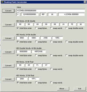
For example, the number 123456.00 as defined in the IEEE 754 standard for single-precision 32-bit floating point numbers appears as follows:
Determining Byte Order
The Modbus protocol itself is declared as a ‘big-Endian’ protocol, as per the Modbus Application Protocol Specification, V1.1.b:
| “Modbus uses a “big-Endian” representation for addresses and data items. This means that when a numerical quantity larger than a single byte is transmitted, the most significant byte is sent first.” |
Big-Endian is the most commonly used format for network protocols – so common, in fact, that it is also referred to as ‘network order’.
Given that the Modbus RTU message protocol is big-Endian, in order to successfully exchange a 32-bit datatype via a Modbus RTU message, the endianness of both the master and the slave must considered. Many RTU master and slave devices allow specific selection of byte order particularly in the case of software-simulated units. One must merely insure that both all units are set to the same byte order.
As a rule of thumb, the family of a device’s microprocessor determines its endianness. Typically, the big-Endian style (the high-order byte is stored first, followed by the low-order byte) is generally found in CPUs designed with a Motorola processor. The little-Endian style (the low-order byte is stored first, followed by the high-order byte) is generally found in CPUs using the Intel architecture. It is a matter of personal perspective as to which style is considered ‘backwards’.
If, however, byte order and endianness is not a configurable option, you will have to determine the how to interpret the byte. This can be done requesting a known floating-point value from the slave. If an impossible value is returned, i.e. a number with a double-digit exponent or such, the byte ordering will most likely need modification.
Practical Help
The FieldServer Modbus RTU drivers offer several function moves that handle 32-bit integers and 32-bit float values. More importantly, these function moves consider all different forms of byte sequencing. The following table shows the FieldServer function moves that copy two adjacent 16-bit registers to a 32-bit integer value.
| Function Keyword | Swap Mode | Source Bytes | Target Bytes |
| 2.i16-1.i32 | N/A | [ a b ] [ c d ] | [ a b c d ] |
| 2.i16-1.i32-s | byte and word swap | [ a b ] [ c d ] | [ d c b a ] |
| 2.i16-1.i32-sb | byte swap | [ a b ] [ c d ] | [ b a d c ] |
| 2.i16-1.i32-sw | word swap | [ a b ] [ c d ] | [ c d a b ] |
The following table shows the FieldServer function moves that copy two adjacent 16-bit registers to a 32-bit floating point value:
| Function Keyword | Swap Mode | Source Bytes | Target Bytes |
| 2.i16-1.ifloat | N/A | [ a b ] [ c d ] | [ a b c d ] |
| 2.i16-1.ifloat-s | byte and word swap | [ a b ] [ c d ] | [ d c b a ] |
| 2.i16-1.ifloat-sb | byte swap | [ a b ] [ c d ] | [ b a d c ] |
| 2.i16-1.ifloat-sw | word swap | [ a b ] [ c d ] | [ c d a b ] |
The following table shows the FieldServer function moves that copy a single 32-bit floating point value to two adjacent 16-bit registers:
| Function Keyword | Swap Mode | Source Bytes | Target Bytes |
| 1.float-2.i16 | N/A | [ a b c d ] | [ a b ][ c d ] |
| 1.float-2.i16-s | byte and word swap | [ a b c d ] | [ d c ][ b a ] |
| 1.float-2.i16-sb | byte swap | [ a b c d ] | [ b a ][ d c ] |
| 1.float-2.i16-sw | word swap | [ a b c d ] | [ c d ][ a b ] |
Given the vairous FieldServer function moves, the correct handling of 32-bit data is dependent on choosing the proper one. Observe the following behavior of these FieldServer function moves on the known single-precision decimal float value of 123456.00:
| 16-bit Values | Function Move | Result | Function Move | Result |
| 0x2000 0x47F1 | 2.i16-1.float | 123456.00 | 1.float-2.i16 | 0x2000 0x47F1 |
| 0xF147 0x0020 | 2.i16-1.float-s | 123456.00 | 1.float-2.i16-s | 0xF147 0X0020 |
| 0x0020 0xF147 | 2.i16-1.float-sb | 123456.00 | 1.float-2.i16-sb | 0x0020 0xF147 |
| 0x47F1 0x2000 | 2.i16-1.float-sw | 123456.00 | 1.float-2.i16-sw | 0x47F1 0x2000 |
Notice that different byte and word orderings require the use of the appropriate FieldServer function move. Once the proper function move is selected, the data can be converted in both directions.
Of the many hex-to-floating point converters and calculators that are available in the Internet, very few actually allow manipulation of the byte and word orders. One such utility can be downloaded HERE. The utility presents the decimal float value of 123456.00 as follows:

