Using an oscilloscope on a RS485 network. For reference purposes we present some scope captures of a typical RS485 line.

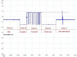
In this capture we had our scope leads connected to the positive signal conductor and ground.
Zone A: Idle State
Zone E: Idle State with Noise
This is the state of the network when all the transmitters have released the line. In this state the conductors float. In many ways this is the most dangerous state for a 485 network to be in since the voltage levels are not defined and vary depending on factors such as the ground potential between devices. If the voltage floats to a level where it looks like a signal then you will see noise bytes on the line. Once a device starts transmitting it pulls the line to a known voltage level so the floating problem is eliminated. Its usually quite easy to recognize these noise bytes because all messages look good but there is noise that precedes the message. Idle state biasing can be used to eliminate this problem because it has the effect of holding the line at a 'known' voltage for the duration of the idle state. Another source of idle state noise is not using the 3rd conductor – the so called signal reference common.
Zone B: The device has enabled it transmitter but has not started transmitting. The line is driven to a known state. The duration of this phase can be controlled by configuration in some devices. If it is too short then it is possible that some of the front of the message may be lost.
Zone C: Unless you have a very high speed scope and the scope can takes a huge number of samples you are unlikely to see each bit in the message. In this capture we can see the bytes (roughly speaking) but not the bits. We were forced to accept this compromise because the number of samples we could capture at a sampling rate high enough to see the bits would mean that we could only capture the 1st couple of bytes of the message and we would have to set the trigger to ignore zone B. Except with a very expensive scope you will be unlikely to be able to see the whole message and all the bits.
Zone
D: We have finished transmitting but the
transmitter is still enabled. Normally the device should disable its transmitter as soon as possible
after
transmitting the last stop bit of the message but since that can be difficult to achieve in the
hardware,
many
devices run a timer to make sure they don't disable the transmitter too soon. The problem with this
approach
is:
1) The longer the time the more potential bandwidth is
lost.
2) The receiving device may have already processed the
message
and
try to send a response by enabling its own transmitter causing collisions.

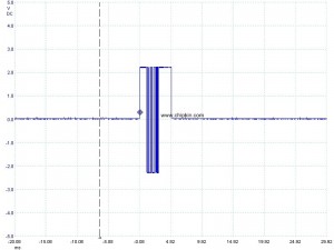
Probes on plus and minus conductors. Segment connected to slave device.

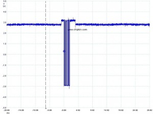
Probes on plus and minus
conductors. This chart represent the capture from a master device with no slaves connected to the
network
leaving the cable ends to float.

I'm looking for a reasonably priced portable oscilliscope. Could you possibly post some type of specifications that one could use to ensure that we buy a scope that can at least perform properly? Looking for at least some baseline specifications needed. Thanks.
Tyler:
Consider the Picoscope 2205A used with a laptop. The software is richly featured. The unit has two 25 MHz inputs with 8 bit resolution and a signal generator.