


We carry the following Modules:
- INTR24-S06-0030: 24 - Interior with 06 - RR9P, switch inputs, 3-CLCDIM4
- INTR24-S06-G010: 24 - Interior with 06 - RR9P, switch inputs, 1-CLCGSM8, 1-CLCDIM4
- INTR24-S12-0010: 24 - Interior with 12 - RR9P, switch inputs, 1-CLCDIM4
- INTR24-S12-001S: 24 - Interior with 12 - RR9P, switch inputs, 1-CLCDIM4, 1-CLCDLS
- INTR24-S12-0020: 24 - Interior with 12 - RR9P, switch inputs, 2-CLCDIM4
- INTR24-S12-002S: 24 - Interior with 12 - RR9P, switch inputs, 2-CLCDIM4, 1-CLCDLS
- INTR24-S12-0B10: 24 - Interior with 12 - RR9P, switch inputs, 1-CLCBnet, 1-CLCDIM4
- INTR24-S12-0B20: 24 - Interior with 12 - RR9P, switch inputs, 1-CLCBnet, 2-CLCDIM4
- INTR24-S12-G000: 24 - Interior with 12 - RR9P, switch inputs, 1-CLCLGSM8
- INTR24-S12-G00S: 24 - Interior with 12 - RR9P, switch inputs, 1-CLCGSM8, 1-CLCDLS
- INTR24-S12-G010: 24 - Interior with 12 - RR9P, switch inputs, 1-CLCGSM8, 1-CLCDIM4
- INTR24-S12-G01S: 24 Interior with 12 - RR9P, switch inputs, 1-CLCGSM8, 1-CLCDIM4, 1-CLCDLS
- INTR24-S12-G020: 24 - Interior with 12 - RR9P, switch inputs, 1-CLCGSM8, 2-CLCDIM4
- INTR24-S12-G02S: 24 Interior with 12 - RR9P, switch inputs, 1-CLCGSM8, 2-CLCDIM4, 1-CLCDLS
- INTR24-S12-GB00: 24 - Interior with 12 - RR9P, switch inputs, 1-CLCGSM8, 1-CLCBnet
- INTR24-S12-GB10: 24 Interior with 12 - RR9P, switch inputs, 1-CLCGSM8, 1-CLCBnet, 1-CLCDIM4
- INTR24-S12-GB20: 24 Interior with 12 - RR9P, switch inputs, 1-CLCGSM8, 1-CLCBnet, 2-CLCDIM4
- INTR24-S12-P000: 24 - Interior with 12 - RR9P, switch inputs, 1-CLCPIM
- INTR24-S12-P00S: 24 - Interior with 12 - RR9P, switch inputs, 1-CLCPIM, 1-CLCDLS
- INTR24-S12-PB00: 24 - Interior with 12 - RR9P, switch inputs, 1-CLCPIM, 1-CLCBnet
- INTR24-S18-0010: 24 - Interior with 18 - RR9P, switch inputs, 1-CLCDIM4
- INTR24-S18-001S: 24 - Interior with 18 - RR9P, switch inputs, 1-CLCDIM4, 1-CLCDLS
- INTR24-S18-0020: 24 - Interior with 18 - RR9P, switch inputs, 2-CLCDIM4
- INTR24-S18-002S: 24 - Interior with 18 - RR9P, switch inputs, 2-CLCDIM4, 1-CLCDLS
- INTR24-S18-0B10: 24 - Interior with 18 - RR9P, switch inputs, 1-CLCBnet, 1-CLCDIM4
- INTR24-S18-0B20: 24 - Interior with 18 - RR9P, switch inputs, 1-CLCBnet, 2-CLCDIM4
- INTR24-S18-G000: 24 - Interior with 18 - RR9P, switch inputs, 1-CLCLGSM8
- INTR24-S18-G00S: 24 - Interior with 18 - RR9P, switch inputs, 1-CLCGSM8, 1-CLCDLS
- INTR24-S18-G010: 24 - Interior with 18 - RR9P, switch inputs, 1-CLCGSM8, 1-CLCDIM4
- INTR24-S18-G01S: 24 Interior with 18 - RR9P, switch inputs, 1-CLCGSM8, 1-CLCDIM4, 1-CLCDLS
- INTR24-S18-G020: 24 - Interior with 18 - RR9P, switch inputs, 1-CLCGSM8, 2-CLCDIM4
- INTR24-S18-GB00: 24 - Interior with 18 - RR9P, switch inputs, 1-CLCGSM8, 1-CLCBnet
- INTR24-S18-GB10: 24 Interior with 18 - RR9P, switch inputs, 1-CLCGSM8, 1-CLCBnet, 1-CLCDIM4
- INTR24-S18-P000: 24 - Interior with 18 - RR9P, switch inputs, 1-CLCPIM
- INTR24-S18-P00S: 24 - Interior with 18 - RR9P, switch inputs, 1-CLCPIM, 1-CLCDLS
- INTR24-S18-PB00: 24 - Interior with 18 - RR9P, switch inputs, 1-CLCPIM, 1-CLCBnet
- INTR24-S24-0010: 24 - Interior with 24 - RR9P, switch inputs, 1-CLCDIM4
- INTR24-S24-001S: 24 - Interior with 24 - RR9P, switch inputs, 1-CLCDIM4, 1-CLCDLS
- INTR24-S24-0020: 24 - Interior with 24 - RR9P, switch inputs, 2-CLCDIM4
- INTR24-S24-0B10: 24 - Interior with 24 - RR9P, switch inputs, 1-CLCBnet, 1-CLCDIM4
- INTR24-S24-G000: 24 - Interior with 24 - RR9P, switch inputs, 1-CLCGSM8
- INTR24-S24-G00S: 24 - Interior with 24 - RR9P, switch inputs, 1-CLCGSM8, 1-CLCDLS
- INTR24-S24-G010: 24 - Interior with 24 - RR9P, switch inputs, 1-CLCGSM8, 1-CLCDIM4
- INTR24-S24-GB00: 24 - Interior with 24 - RR9P, switch inputs, 1-CLCGSM8, 1-CLCBnet
- INTR24-S24-P000: 24 - Interior with 24 - RR9P, switch inputs, 1-CLCPIM
- INTR24-S24-P00S: 24 - Interior with 24 - RR9P, switch inputs, 1-CLCPIM,1-CLCDLS
- INTR24-S24-PB00: 24 - Interior with 24 - RR9P, switch inputs, 1-CLCPIM,1-CLCBnet
CLCINTR24 24 Relay Interior Capacity
The CLCINTR24 or CLCINTR24-xxx-xxxx is the interior frame for a LightSweep relay panel with 24-relay capacity. The same frame is used for dimming panels. The complete assembly also includes one of the following:
- Metal Tub (CLCTUBxx)
- Power Supply (RPWRxxxx)
- Cover (CLCCOVxxSL)
Features
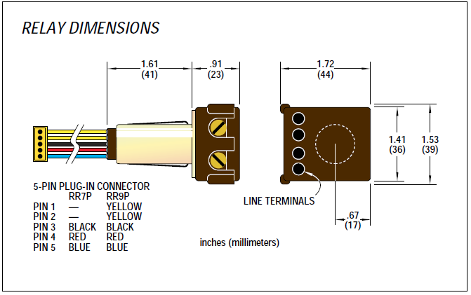
Pre-wired RR9P (5-wire) or RR7P (3-wire) plug-in relays.
Push-button override with LED status indication for each relay.
Interior components - (specified in the complete description of INTxyy-xxx-xxxx)):
- CLCGSM8 - Eight programmable switch inputs, each "softwired" to any group of relays in the network
- Local Channel push-button control with bi-color LED status indication (ON/OFF/Mixed group). Eight inputs configured for either switch/motion or photocell inputs.
- CLCRMS6 (CLRM6) - Relay module for 6 relays RR9P (RR7P) relays.
- CLCDIM - Four input/outputs for controlling 0-1vdc dimming ballast, each output can control up to 50 0-10v dimmable ballasts or LED drivers.
- CLCDLS - data line scheduler/programmer - 8-schedules.
Maximum of 99 nodes per CAN segment.
Note: product may be different than appears on Image as it depends on the modules and Relays Required.
CLCTUBxx Metal Tub
The CLCTUBxx is the tub for CLC rated Lighting Automation panel.
Separating the modules simplifies installation. The tub can be mounted early to allow conduit installation and rough-in wiring. The interior, which includes the relays and terminations, simply slides into the tub. The lighting circuits and low voltage control wiring can then be terminated and the cover installed.
CLCCOVxxSL Cover
The CLCCOVxxSL is a surface mounted, hinged, lockable cover for 12, 24, 36, 48 CLC Lighting Automated Panels.
Separating the modules simplifies installation. The Cover can be mounted early to allow conduit installation and rough-in wiring. The interior, which includes the relays and terminations, simply slides into the tub. The lighting circuits and low voltage control wiring can then be terminated and the cover installed.
CLCXFRxx Control Transformer
The CLCXFRxx is the power supply for the INTERxx-xxx-xxxx Lighting Automation panel.
Features
Overcurrent protection. Transformer automatically goes off when overloaded and resets when the fault is removed.
Two separate 50VA transformers. Separate transformers for relays and intelligence modules provides relay wiring flexibility while ensuring a stable power source for the electronic options.
GE-MOV voltage spike protection. metal Oxide Varistors protect all downstream electronics from powerline voltage spikes.
RR7P and RR9P Relays
GE RR SERIES RELAYS HAVE SERVED as the heart of low voltage lighting controls for over 40 years. The basic power switching device, the relay serves as the foundation of a building’s lighting control solution.
GE’s Remote Control panels and frames are configured for either RR7P or RR9P relays with a five-pin female connector. The user can simply remove a knockout in the low voltage barrier, snap the relay into place, and plug it onto the interconnect board.
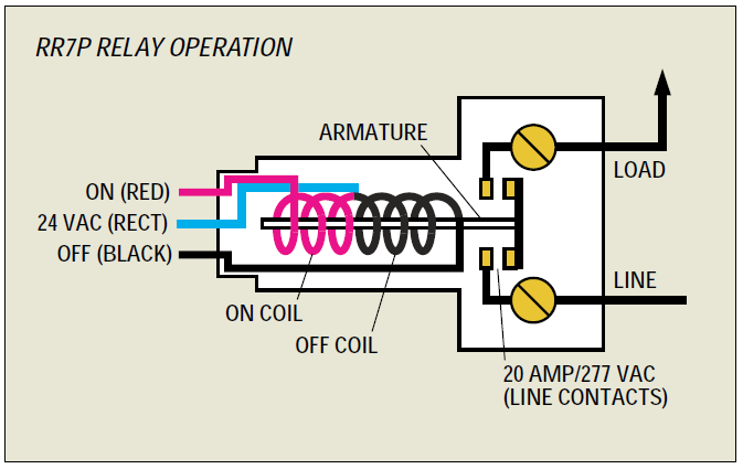
RR7P Operation
Each relay employs a split low-voltage (24V) coil to move the line voltage contact armature to the ON(OFF) latched position. As illustrated on the opposite page for the RR7P, the ON coil moves the armature to the left when a 24 volt control signal is impressed across its leads. The armature latches in the ON position and will remain there until the OFF coil is energized.
This operation provides several key control features:
- Positive action. The relay always goes to the state commanded. For example, multiple OFF commands will keep the contacts in the OFF position.
- Stable operation. Since the relay latches in the ON or OFF position, power outages do not result in a change of state.
- Minimal power consumption. Control power is only required when the relay changes state.
- Ability to support multiple input devices. After the relay responds to a momentary pulse, it is then “free” to accept another pulse from any other control devices wired to it. The relay position is always controlled by the last signal.
RR9P Operation
GE RR9P relays are mechanical latching-type devices for direct plug-in to a GE Lighting Automation Panel. Pilot contact provides status feedback through LED indicators mounted on Rinterxxyy. They require only momentary 24 volt rectified AC switch circuits. Coil design resists burnout that could occur if equipment or operational failure energized the relay for an extended period of time. All GE low voltage relays may be used to full rated capacity for tungsten filament, ballast or resistive loads.
The RR9P includes an auxiliary contact on the low-voltage side of the armature to provide status indication for pilot light switches or indicator lights for remote annunciation of lighting status. It is also used to provide status information to more highly automated GE TLC systems
Replay Catalog numbers and Descriptions
- RR7P: Standard 3-wire relay with 5-pin connector
- RR9P: Isolated pilot contact 5-wire relay with 5-pin connector
- RR7: Standard 3-wire relay with stripped leads
- RR8; Pilot contact 4-wire relay with stripped leads
- RR9: Isolated pilot contact 5-wire relay with stripped leads
- RR7EZ: Standard 3-wire relay with spade terminals
- RR8EZ: Pilot contact 4-wire relay with spade terminals
- RR9EZ: Isolated pilot contact 5-wire relay with spade terminals
CLCRM6/CLCRMS6 Relay Module
The CLCRMx6 Relay Module will connect up to six RR style relays to the modular lighting control system. Supports relays with or without feedback with LED status indication and pushbutton toggle operation.
The CLCRMS6 has six switch input terminals with pilot light operation for relays which have the optional feedback, or jumper selectable locator light operation for those without.
Features
- Controls up to 6 relays with or without feedback
- Optional relay control via 6 hardwired switch inputs
- Color-coded spring-type terminals for switch wiring
- Pushbutton programming capable for basic operation
- Toggle relay state via pushbutton
- Jumper selectable for Pilot or Location switch functionality
- Communicating on CAN lighting network
Application
The CLCRMx6 provides control of up to six relays per module allowing a lighting panel to be built up based on the number of relays the panel requires and reducing costs. This also allows for simple expansion of a panel to add in additional modules and relays until the panel capacity is reached. The RMS6 version of the module has six 2-position (On/Off) terminals with pilot/locator functionality. These terminals allow for 3-wire and 2-wire Momentary and Maintained switch operation based on how the switches are wired to the terminals.
Order the controller and desired options with the following product numbers:
- CLCRM6: 6 Relay Control Module
- CLCRMS6: 6 Relay Control Module with 6 direct-control switch inputs
CLCGSM8 8 Group Input Module
The CLCGSM8 Group Switch Module will connect up to eight inputs to the Modular Lighting Control System. Through the color-coded spring clip terminals, the device supports switches, photocells and motion sensors. When not used for switches, the pilot light terminals may be configured to provide power to the connected sensors simplifying installation.
Pushbutton programming provides a simple means of assigning the input to groups of relays and other group inputs on the lighting network. Module doubles as a power injector distributing power to the panel's relay modules and the lighting network, providing status indication for network power monitoring.
Features
- Connects up to 8 inputs
- Inputs can be configured for switches, photocells or motion sensors
- Color-coded spring-type terminals for switch wiring
- Pushbutton programming capable for basic operation
- Toggle switch state via pushbutton
- Jumper selectable for binary contacts or analog photocell
- Communicating on CAN lighting network
Application
The CLCGSM8 provides a way to map a variety of system input devices such as switches, motion sensors and photocells to relays and smaller nested lighting groups. Status indication on the device is derived from the status of the devices which is under its control providing immediate useful feedback about them. Pushbutton programming allows users to quickly program basic group switch to relay associations, while more advanced motion sensor and photocell operation is programmed via software or the data line scheduler.
Order the controller and desired options with the following product numbers:
- CLCGSM8 - 8 Group Input Module
CLCDIM4 4 Channel Dimming Module
The CLCDIM4 dimming module controls four dimming channels. Through the color-coded spring terminals, the device provides 0-10V dimming controlled by a photocell for daylighting operations, as well as advanced scene control via devices in the CLC network.
The module can be powered via the CLC network or can double as a power injector distributing power to the panel’s relay modules and the lighting network, providing status indication for network power monitoring.
Features
- Connects up to 4 photocell inputs
- Connects up to 4 0-10V dimming outputs
- Color-coded spring-type terminals for photocell and ballast
- Closed-loop daylighting control build into channel
- LED output indication of level
- Jumper selectable for network or transformer power
- Communicating on CAN lighting network
Application
The CLCDIM4 provides daylighting and analog scene control to the CLC system. The channels daylighting setpoint or analog outputs can be controlled using switches in the CLC system so that operation is coordinated with On/Off relay control of the circuits.
Photocell control provides closed-loop control for indoor type sensors, and open loop control for outdoor, atrium or skylight sensors. Closed loop will allow setpoint control to a given footcandle value, while open loop control will linearly vary the output based on a specified range of the photocell.
Order the controller and desired options with the following product numbers:
- CLCDIM4 - 4 Channel Dimming Module
CLCDLS Touchscreen Dataline Scheduler
The CLCDLS touchscreen Scheduler provides 8 schedules to control any relays or groups in the lighting system. It also provides astronomical clock information, calculating sunrise and sunset times based on UTC and location. 8 additional lighting control groups are available for Common Area control or other grouping needs.
The device is powered off the same structured cabling which powers the CLCSWTx Network Switches, and provides a user interface into the network for configuring any device in the network independent of where it is located.
Features
- 3.5"Full-Color Touchscreen
- 8 weekly schedules with up to 8 durations per day
- Single or recurring exceptions to each schedule
- Real-time clock with Super-cap backup
- Configuration interface for an entire lighting network
- Astronomical clock functionality
- 8 additional programmable groups
- Communicating and powered from CAN lighting network
Application
The CLCDLS can turn On and/or Off up to 60 individual relays or lighting control groups for each schedule, with scheduling exceptions or astro functionality. Any lighting control group in the network may enable or disable functionality based on time of day by subscribing to any schedule.
The dataline scheduler doubles as a user interface into the lighting network allowing the user to configure, edit and operate all switches, sensors, relays and remote schedules in the system. It can be mounted in the LCP or on a standard electrical wall box for mounting in the space. Each CLCDLS adds 8 schedules to the system, providing scalability for any advanced lighting application scenarios.
Order the controller and desired options with the following product numbers:
- CLCDLS - Touchscreen Dataline Scheduler
CLCBNET BACnet Interface Module
The CLCBNET controller expands the features of a stand-alone Lighting Control System to a fully programmable with computer front-end system, with capability for seamless integration to EMS using the BACnet protocol.
It is a fully programmable native BACnet controller, supporting the BACnet MS/TP, BACnet over Ethernet and BACnet IP.
The CLCBNET maps the lighting system’s objects: relays, analog I/O’s (dimming channels, photocell inputs) and provides control and schedule functionality.
Features
- Controls up to 99 CAN devices
- Dynamically learns all devices on the CAN bus and displays the object configuration.
- Allows for remote programming and monitoring via Ethernet or TCP/IP
- Push-button switch for automatic program transfer to CAN devices
- Custom programming
- Event logging and trending, alarming
Application
CLCBNET is used for applications requiring computer front-end for programming and monitoring, integration to EMS using the BACnet protocol, web interface for lighting control system. campus applications with remote buildings or multi-site companies.
Order the controller and desired options with the following product numbers:
- CLCBNET - BACnet Interface Module
Specifications
Description: Lighting Automation panel Interior
Catalog#: CLCINTR24
Operating: 0-55C (32-131F)
Environment: 0-95% RH, non-condensing. Non-corrosive atmhsphere.
Codes: UL 916 Energy Management CAS Certified
Finish: Painted Grey ASA 6-1
Description: Lighting Automation panel Tub
Catalog#: CLCTUBxx
Operating: 0-55C (32-131F)
Environment: 0-95% RH, non-condensing. Non-corrosive atmhsphere.
Codes: NEMA 1 Rated UL916 Energy Management
Finish: Painted Gray ASA6-1
Description: Surface, Hinged, Lockable Cover
Catalog#: CLCCOVxxSL
Operating: 0-55C (32-131F)
Environment: 0-95% RH, non-condensing. Non-corrosive atmhsphere.
Codes: NEMA 1 Rated UL916 Energy Management
Finish: Painted Gray ASA6-1
Description: Lighting Automation panel Power Supply
Catalog#: CLCXFRxx
Operating: 0-55C (32-131F)
Environment: 0-95% RH, non-condensing. Non-corrosive atmhsphere.
Weight: 6 lbs/2.7kg
Voltage/Hz:
- CLCXFR347V: 347/50-60
- CLCXFRMV: 115/50-60, 277/50-60
Mounting: In Interxx-xxx-xxxx
Codes: UL 916 Energy Management CAS Certified
Description: Latching Relay with Plug-in Connector, Pilot Contacts
Catalog#: RR7P, RR9P, RR7, RR8, RR9, RR7EZ, RR8EZ, RR9EZ
Operating Environment
Temperature: 0-60C (32-140F)
Relative Humidity: 10-95% RH, non-condensing.
Atmosphere: Non-corrosive atmosphere. Non-explosive atmosphere.
Vibration: Stationary applications Nema Level A
Endurance
50,000 cycles, full load
100,000 cycles, no load
Line-Voltage Characteristics
Contacts: SPT maintained (Mechanical latching)
Terminals:
- 2 Terminals
- 2 Back-wiring holes per terminal
- Feedthrough wiring
- Screw actuated clamps for use with #14-10 AWG solid or stranded copper wire only
Low-Voltage Characteristics
Split coil: 1/2 for "ON", 1/2 for "OFF"
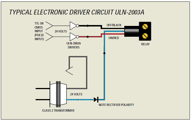
Compatible with standard interface/driver, ULN-2003A Darlington transition arrays
Operating Voltage-Nominal
- 24-29 VAC (±10%) rectified (minimum at relay = 21 VAC rectified)
- 30-38 VDC (±10%) filtered
Note: Do not use DC with pilot or locator switches
Duty rating: Momentary
Minimum Activating Pulse Time: 50 Milliseconds
Coil Impedance: 75-85 Ohms at 60 Hz Unrectified
55-60 Ohms DC Resistance
Pilot Contact: 1 A 24-29 VAC Resistive
Rated Capacity
Lamp Load:
- 20 amp Tungsten Filament 125VAC
- 30 amp Ballast 277 VAC
Resistive Load: 30
Motor Load:
- 1/2 HP @ 110-125 VAC
- 1 1/2 HP @ 347 VAC
Codes: UL Listed 508G, CSA. Mounts in standard 1/2” KO, .865”-.875” diameter, 14 or 16 gauge material
Operates in any position.
Inputs
- 6 2-position closed-contact switch inputs (RMS6)
Outputs
- Compatible with RR7 and RR9 relays
Technology
- 32-bit ARM Processor with internal
- A/D, Flash and RAM
Communications Port
- CAN Network @40k bps
Device Address:
- Set via rotary dials
- Address range: 1 to 99
Connectors Inputs:
- spring-clip terminal connectors
- Outputs: 5-pin MTA
- Network/Power: (2) 4-pin MTA
Wiring Class
- Class 2
Power
- 24 VAC
- 4 VA
Ambient
- 32° to 131°F (0° to 55°C), with enclosure
- 10-90% RH (non-condensing)
Dimensions
- 5 1/2 x 4 3/4 x 1 1/8 in. (14 x 12.1 x2.9 cm) with housing
- 0.34 lb. (155g) with housing
Compliance
- CE
- FCC
Approvals/Standards:
- cUL Listed - Energy Management
Inputs\Outputs
- 8 4-position connectors for closed-contact switch/motion/photocell inputs including pilot/locator light outputs
Technology
- 32-bit ARM Processor with internal A/D, Flash and RAM
Communications Port
- CAN Network @40k bps
Device Address:
- Set via rotary dials
- Address range: 1 to 99
Connectors Inputs:
- Spring-clip terminal connectors
- Outputs: 5-pin MTA
- Network/Power: (2) 4-pin MTA, (2) RJ45
Wiring Class
- Class 2
Power
- 24 VAC
- 14.5 VA
Ambient
- 32° to 131°F (0° to 55°C), with enclosure
- 10-90% RH (non-condensing)
Dimensions
- 5 1/2 x 4 3/4 x 1 1/8 in. (14 x 12.1 x2.9 cm) with housing
- 0.34 lb. (155g) with housing
Compliance
- CE
- FCC
Approvals/Standards:
- cUL Listed - Energy Management
Inputs\Outputs
- 8 4-position connectors for closed-contact switch/motion/photocell inputs including pilot/locator light outputs
Technology
- 32-bit ARM Processor with internal A/D, Flash and RAM
Communications Port
- CAN Network @40k bps
Device Address:
- Set via rotary dials
- Address range: 1 to 99
Connectors Inputs:
- Spring-clip terminal connectors
- Outputs: 5-pin MTA
- Network/Power: (2) 4-pin MTA, (2) RJ45
Wiring Class
- Class 2
Power
- 24 VAC
- 13 VA
Ambient
- 32° to 131°F (0° to 55°C), with enclosure
- 10-90% RH (non-condensing)
Dimensions
- 5 1/2 x 4 3/4 x 1 1/8 in. (14 x 12.1 x2.9 cm) with housing
- 0.34 lb. (155g) with housing
Compliance
- CE
- FCC
Approvals/Standards:
- cUL Listed - Energy Management
Technology
- 32-bit ARM Processor with internal A/D, Flash and RAM
Communications Port
- CAN Network @40k bps
Device Address:
- Set via rotary dials
- Address range: 1 to 99
Connectors Inputs:
- Network/Power: (2) RJ45
Wiring Class
- Class 2
Power
- 24 VAC
- 3 VA
Ambient
- 32° to 131°F (0° to 55°C), with enclosure
- 10-90% RH (non-condensing)
Dimensions
- 5 1/2 x 4 3/4 x 1 1/8 in. (14 x 12.1 x2.9 cm) with housing
- 0.34 lb. (155g) with housing
Compliance
- CE
- FCC
Approvals/Standards:
- cUL Listed - Energy Management
Communication Ports
- CAN lighting network
- Communication speed 40 kbps
- Maximum 99 nodes per CAN segment
- Ethernet
- 3-Port 10/100 Switch
- BACnet IP, BACnet Ethernet
- USB – 2 USB ports
Inputs
- Two push-buttons (Reset, Transfer)
Technology
- ARM Processor with internal Flash and RAM
- Real-time clock
- Ultra capacitor backup for RTC
Device Address:
- Set via rotary dials
- Address range: 1 to 99
Connectors Inputs:
- CAN Network 3-pin terminal
- Ethernet – 3-port RJ45 connector
- Power: 2-pin terminal
- BACnet RS485: 3-pin terminal
Wiring Class
- Class 2
Power
- 24 VAC
- 4 VA
Ambient
- 32° to 131°F (0° to 55°C), with enclosure
- 10-90% RH (non-condensing)
Dimensions
- 5”x5.4”x2.6”
Compliance
- FCC
Approvals/Standards:
- cUL Listed - Energy Management