Chipkin Automation Systems GE-TLC Driver Manual
Driver Manual
(Supplement to the FieldServer Instruction Manual)
FS-8700-108
GE-TLC
(GE Total Lighting Control)
Driver
Driver Version:
Document Revision:
1. GE-TLC Driver Description
This serial driver allows connectivity to a GE-TLC network by providing data transfer to the RLINK device. The RLINK device is provided by GE Lighting Controls as a gateway between its proprietary network and building automation networks. Thus to provide data transfer between a 3rd party protocol such as BACNet, it is necessary to connect the BACnet network to the RLINK by means of a FieldServer.
The driver may be configured as a client or server. The Client functionality is fully documented and supported. The FieldServer cannot be used as a substitute for the RLINK device – for this
reason the server side functionality is not documented. If you are interested using the server side please contact the sales group.
As a client the driver is capable of :
• polling for status data,
• sending commands to operate the relays,
• sending commands as if a PSS switch had been operated,
• receiving unsolicited status messages from the TLC network.
The driver can be configured as an adapter – a device which reads a predefined data set and automatically make its available as a set of BACnet data objects. More information is provided in Appendix A.1
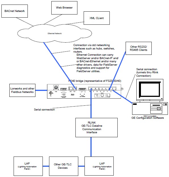
The driver can support a simultaneous connection for a PC running TLC configuration software. More information is provided in Appendix C
| FIELDSERVER MODE | NODES | COMMENTS |
| CLIENT | 9999 | ONLY ONE RLINK DEVICE MAY BE CONNECTED TO A SINGLE PORT ON THE FIELDSERVER. HOWEVER, EACH RLINK DEVICE MAY FORM PART OF A NETWORK OF LIGHTING PANELS (NODES).THE DRIVER DOES NOT LIMIT THE NUMBER OF NODES THAT MAY BE POLLED VIA THE RLINK. |
| SERVER | N/A |
2. Driver Scope of Supply
2.1 Supplied by FieldServer Technologies for this driver
| FieldServer TechnologiesPART # | Description |
| FS-8915-10 | UTP cable (7 foot) for Ethernet connection |
2.2 Provided by the Supplier of 3rd Party Equipment
2.2.1 Required 3rd Party Hardware
| Part # | Description |
| GE R-LINK DEVICE | This device allows 3rd party devices to connect to a GE-TLC network. |
2.2.2 Required 3rd Party Software
None required to enable this driver/
2.2.3 Required 3rd Party Configuration
None required to enable this driver/
2.2.4 Optional Items
| PART # | Vendor/Manufacturer | Description |
3. Hardware Connections
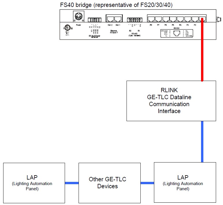
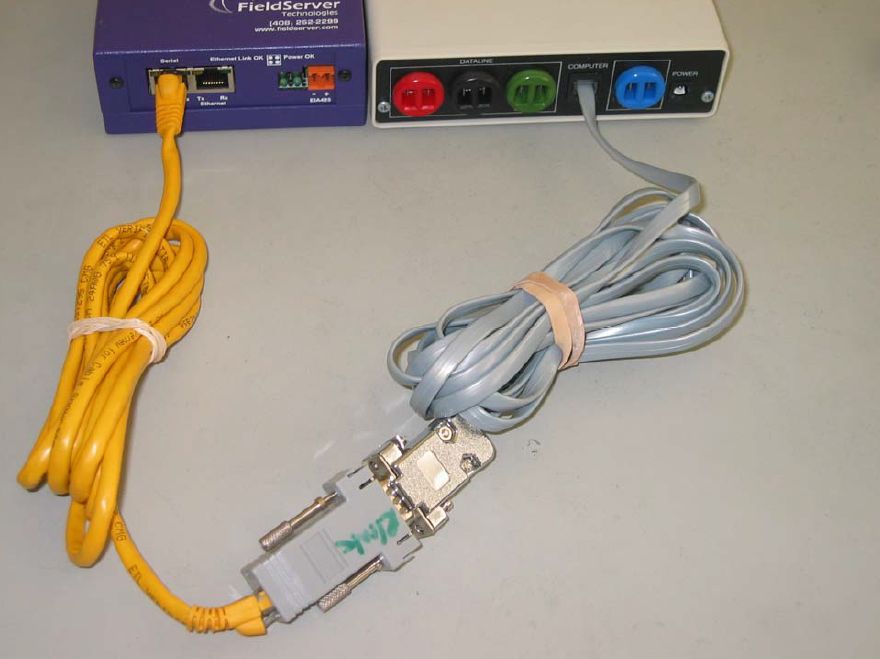
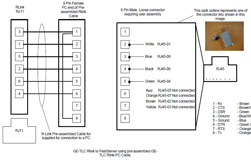
The FieldServer is connected to the R-Link Device as shown in connection drawing.
Configure the R-Link according to manufacturer's instructions
3.1 Block Diagram
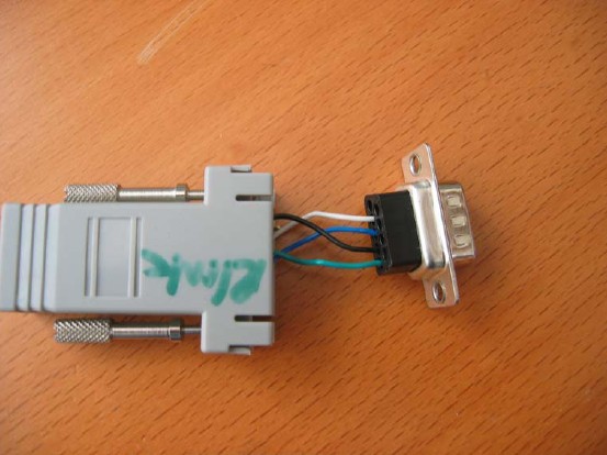
3.2 Connection Photo – FS20 shown as typical
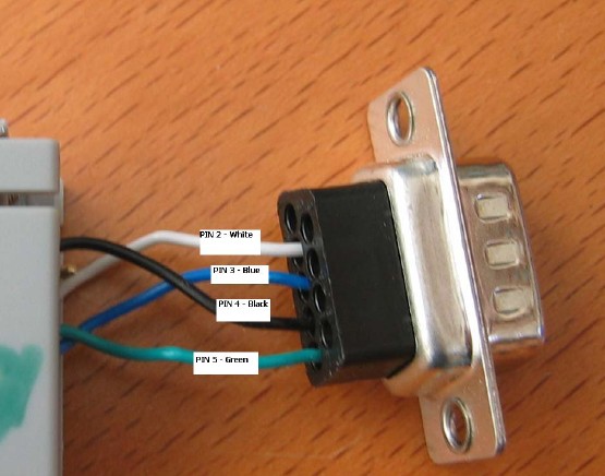
3.3 Cable Diagram – Using A Serial Cable
Note: On FS30 series only P2 can be used for connection to the Rlink.
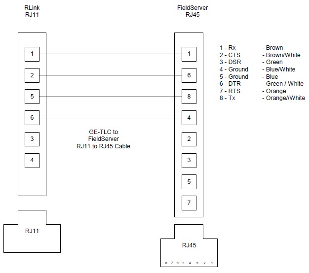
3.4 Cable Diagram – RJ12 direct to RJ45
3.5 Hardware Connection Tips / Hints
3.5.1 Two or more Rlink's on the same network ?
If there are two or more RLINK's on the same network this could present a problem if the driver is not configured correctly. The reason is as follows. Normally the FieldServer is configured as a client. It polls for data and expects responses and can also process unsolicited status updates sent when something changes. If there is another RLINK on the network and it is being used by other client software such as the GE Software or Wincontrol then the FieldServer will receive a copy of the polls sent by that software as all network messages are sent to the each RLINK. When a copy of the poll is received the FieldServer will not know how to respond and this will cause problems. The problem is easily resolved by setting the connection parameter called 'TLC_Server_Enabled' to 'No'. See section 4.2
4. Configuring the FieldServer as a GE-TLC Driver Client
For a detailed discussion on FieldServer configuration, please refer to the FieldServer Configuration Manual. The information that follows describes how to expand upon the factory defaults provided in the configuration files included with the FieldServer (See ".csv" sample files provided with the FieldServer).
This section documents and describes the parameters necessary for configuring the FieldServer to communicate with a GE-TLC Driver Server.
4.1 Data Arrays/Descriptors
The configuration file tells the FieldServer about its interfaces, and the routing of data required. In order to enable the FieldServer for GE-TLC Driver communications, the driver independent FieldServer buffers need to be declared in the "Data Arrays" section, the destination device addresses need to be declared in the "Client Side Nodes" section, and the data required from the servers needs to be mapped in the "Client Side Map Descriptors" section. Details on how to do this can be found below.
Note that in the tables, * indicates an optional parameter, with the bold legal value being the default.
| Section Title | ||
| Data_Arrays | ||
| Column Title | Function | Legal Values |
| Data_Array_Name | Provide name for Data Array | Up to 15 alphanumericcharacters |
| Data_Array_Format | Provide data format. Each Data Array can only take on one format. | Float, Bit, UInt16, SInt16, Packed_Bit, Byte, Packed_Byte, Swapped_Byte |
| Data_Array_Length | Number of Data Objects. Must be larger than the data storage area required by the Map Descriptors for the data being placed in this array. | 1-10,000 |
Example
// Data Arrays
Data_Arrays
Data_Array_Name, Data_Array_Format, Data_Array_Length
DA_AI_01, UInt16, 200
DA_AO_01, UInt16, 200
DA_DI_01, Bit, 200
DA_DO_01, Bit, 200
4.2 Client Side Connection Descriptions
| Section Title | ||
| Connections | ||
| Column Title | Function | Legal Values |
| Port | Specify which port the device is connected to the FieldServer. For FS30 Series bridges, only P2 can be used as the Primary serial port because of the DTR signaling which is not present on P2. | P1-P8, R1-R21 |
| Protocol | Specify protocol used | GE-TLC, GE-Total-Lighting or TLC |
| Baud* | Specify baud rateThe RLINK device self senses the baud rates in this sequence (in this sequence: 300, 19200, 9600, 4800, 2400, 1200. The FieldServer supports all standard baud rates between 300 and 115200 | 110 – 115200, standard baud rates only |
| Parity* | Specify parity | RLINK supports EvenDriver Supports: Even, Odd, None,Mark, Space |
| Data_Bits* | Specify data bits | RLINK supports 8,Driver supports 7,8 |
| Stop_Bits* | Specify stop bits | RLINK supports 1Driver supports 1,2 |
| Handshaking* | Specify hardware handshaking | None |
| Poll-Delay* | Time between internal polls | 0-32000 seconds, 1 second |
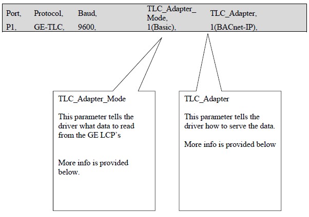
| TLC_Adapter* | Specified when using the driver in adapter mode. See section Appendix A.1 | |
| TLC_Adapter_Mode* | Specified when using the driver in adapter mode. See section Appendix A.1 | |
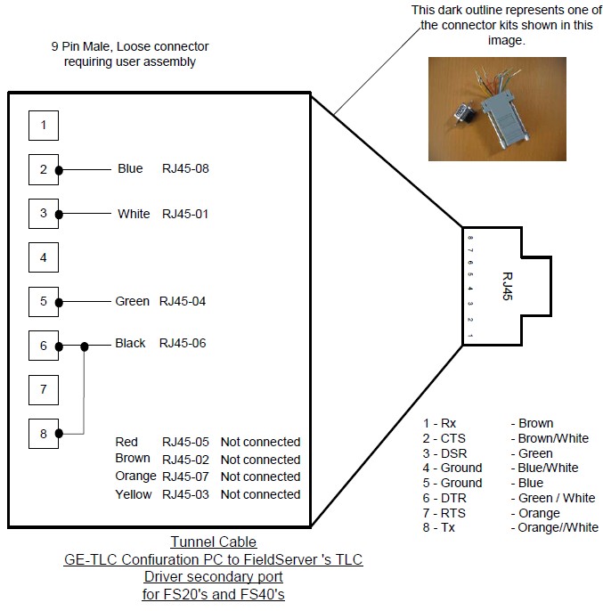
| Secondary_Port* | Specify this parameter if you want a secondary device (e.g.Computer running GE Configuration Software). This port will have the same connection properties as the primary port. It is not possible to the port at a different baud rate.
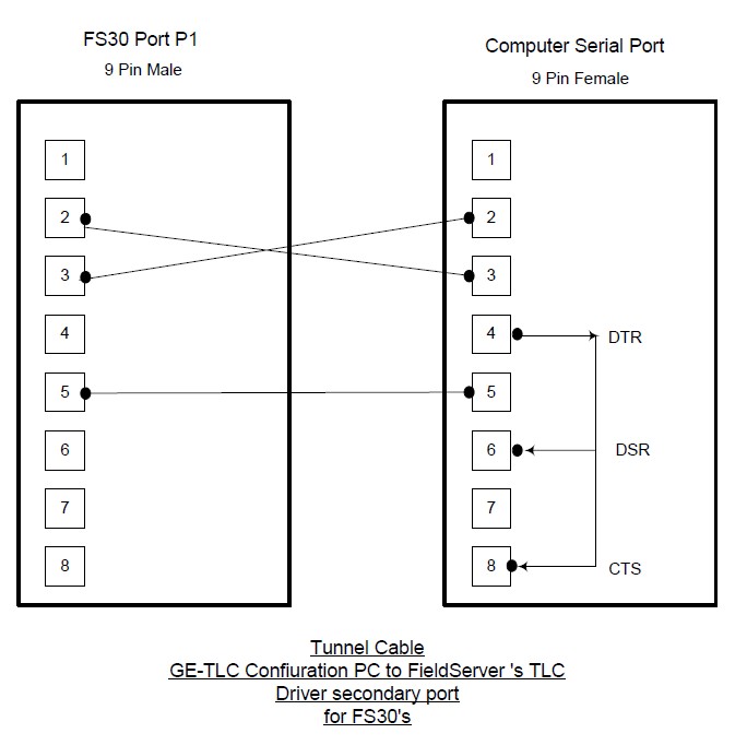
For FS30 Series bridges only P1 can be used as the secondary connection. | P1-P8, R1-R22 |
| TLC_Tunnel_Delay* | Specified in milliseconds.When the driver is configured to allow a PC running configuration software to tunnel through the Rlink connection the driver suspends the normal polling process. The duration of the suspension is controlled by this parameter. Read more about the tunnel in Appendix C | Default is 2000 |
| TLC_Server_Enabled | If set to No then the driver will ignore all poll messages that itreceives. If set to yes, then the driver can respond to polls but must be configured correctly. Please read section 3.5.1 for more information. | No, Yes. |
| Tunnel_Option | In Mode zero, when a message arrives from the tunnel port, the driver suspends polling until the TLC_Tunnel_Delay has expired. The timer is restarted with each new message. The suspension of polling means that the FieldServer will not read status data or write commands to the TLC devices. In Mode=1, the tunnel also suspends polling but does allow command to the relays to be sent immediately. The driver does not wait for a response and thus cannot report the success of the operation. Read more about the tunnel in Appendix C | 0, 1 |
1Not all ports shown are necessarily supported by the hardware. Consult the appropriate Instruction manual for details of the ports available on specific hardware.
2Not all ports shown are necessarily supported by the hardware. Consult the appropriate Instruction manual for details of the ports available on specific hardware.
Example
// Client Side Connections
Connections
Port, Protocol, Baud, Parity, Handshaking, Poll_Delay
P1, GE-TLC, 9600, None, None, 0.100s
Example – Configured as Tunnel for PC doing configuration.
// Client Side Connections
Connections
Port, Protocol, Baud, Parity, Secondary_Port,
P1, GE-TLC, 9600, None, P2
4.3 Client Side Node Descriptors
| Section Title | ||
| Nodes | ||
| Column Title | Function | Legal Values |
| Node_Name | Provide name for node | Up to 32 alphanumeric characters |
| Node_ID | The LCP or PSS node number. | 1-9999 |
| Protocol | Specify protocol used | GE-TLC, GE-Total-Lighting or TLC |
| Connection | Specify which port the device is connected to the FieldServer | P1-P8, R1-R23 |
| PLC_Type | In adapter mode this parameter tells the driver what kind of node to create and what Map Descriptors to create. Read more in section Appendix A.1 | PSS-SwitchPSS-TrapLINK LCP12 LCP24 LCP48 LCP(Unknown) Type-Unknown |
Example
// Client Side Nodes
Nodes
Node_Name, Node_ID, Protocol, Connection
PLC 1, 1, Modbus_RTU, P8
3Not all ports shown are necessarily supported by the hardware. Consult the appropriate Instruction manual for details of the ports available on specific hardware.
4.4 Client Side Map Descriptors
4.4.1 FieldServer Related Map Descriptor Parameters
| Column Title | Function | Legal Values |
| Map_Descriptor_Name | Name of this Map Descriptor | Up to 32 alphanumeric characters |
| Data_Array_Name | Name of Data Array where data is to be stored in the FieldServer | One of the Data Array names from "Data Array" section above |
| Data_Array_Offset | Starting location in Data Array | 0 to maximum specified in "Data Array" section above |
| Function | Function of Client Map Descriptor | RDBC, WRBC, WRBX |
4.4.2 Driver Related Map Descriptor Parameters
| Column Title | Function | Legal Value |
| Node_Name | Name of Node to fetch data from | One of the node namesspecified in "Client Node Descriptor" above |
| Data_Type | Data type | Register, Coil, AI, DI |
| Length | Length of Map DescriptorSee the examples for more specific information. | Positive whole numbers. |
| Address | When writing to a panel the address is used as the relay number. When reading data the address is generally ignored.
See the examples for more specific information. | Zero and Positive wholenumbers. |
| TLC_Function | Tells the driver what data to read or write.Examples illustrate the use of each one. | "Override Single Relay""Schedule Action Single Relay" "Clean Action Single Relay" "Shed Action Single Relay" "Relay Status" "Relay Failures" "Module Status" "Link Status" "Unsol Relay Status" "Unsol Relay Failures" "Unsol Module Status" "Unsol Link Status" "Unsol PSS Control" "Override Relay Group" |
4.4.3 Timing Parameters
| Column Title | Function | Legal Values |
| Scan_Interval | Rate at which data is polled | ->0.001s |
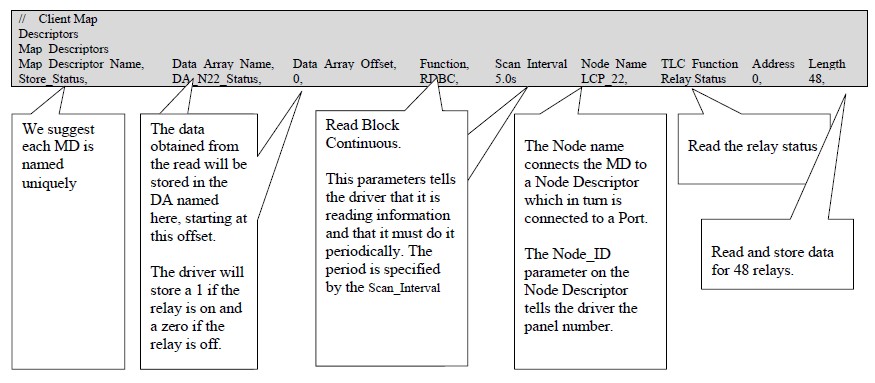
4.5 Map Descriptor (MD) Example 1 – Read Relay Status.
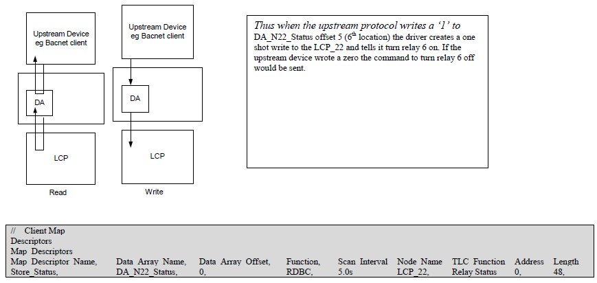
This Map Descriptor (MD) reads the status of the relays on a LCP and stores the result. The length of 48 allows the driver to read andstore data for 48 relays. The address parameter is not used because the driver will read the data for all relays and will start storingrelay #1's status information at offset 0 in the Data Array (DA) called DA_N22_Status. Relays #2's status will be stored in offset 1.This read task will be executed every 5 seconds. The TLC_Function parameter tells the driver what data to read.
If a relay status changes the LCP sends an unsolicited message reporting the change. When the driver receives the message it willlook for a place to store the data. If the message is from the LCP_22 then this MD will be used to store the data. Thus the data in theassociated DA may be updated more often than the scan interval.
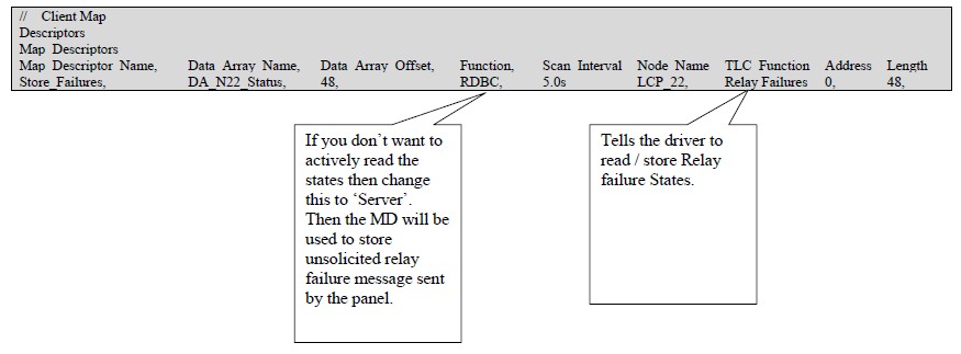
4.6 Map Descriptor (MD) Example 2 – Read Relay Failures.
This example is almost the same as example 1 except that in this example we are not reading the relay status but the relay failurestate. If a relay has failed the driver stores a 1 and if the relay is in a non-failed state the driver stores a zero.
This Map Descriptor (MD) stores the failure state for relay #1 in offset 48 of the Data Array (DA) called DA_N22_Status. Relays #2'sfailure state will be stored in offset 49.
If a relay fails the LCP sends an unsolicited message reporting the change. When the driver receives the message it will look for aplace to store the data. If the message is from the LCP_22 then this MD will be used to store the data. Thus the data in the associatedDA may be updated more often than the scan interval.
4.7 Map Descriptor (MD) Example 3 – Read Module (LCP/LAP) Status.
In this MD the driver reads the status of the module – this is the LCP or LAP status and not the status of the relays on the module. Thedriver stores 8 consecutive bits. In this example the Data_Array_Offset is 96 and thus the driver stores the 1st of the 8 at offset 96.
Bit 1 : Clock set if=1
Bit 2: Program set if=l
Bit 3: Relay failure if=1 . (cleared by clear relay failure indicators or when last relay failure self-clears)
Bit 4: Reserved
Bit 5: =1 when driver 1 is in place (relay 1-12)
Bit 6: =1 when driver 1 is in place (relay 13-24)
Bit 7: =1 when driver 1 is in place (relay 25-36)
Bit 8: =1 when driver 1 is in place (relay 27-48)
If the module status changes the module sends an unsolicited message reporting the change. When the driver receives the message itwill look for a place to store the data. If the message is from the LCP_22 then this MD will be used to store the data. Thus the data inthe associated DA may be updated more often than the scan interval.
// Client Map
Descriptors
Map_Descriptors
Map_Descriptor_Name, Data_Array_Name, Data_Array_Offset, Function, Scan_Interval Node_Name TLC_Function Address Length
Store_Mod_Status, DA_N22_Status, 96, RDBC, 5.0s LCP_22, Module Status, 0, 8,
4.8 Map Descriptor (MD) Example 4 – Passively listening for Relay Status changes, Relay Failures Module Status changes.
This is achieved by using the same MD's as in examples 1-3 but change the function to 'passive'. This means the driver will not pollfor data but by providing the MD's you define a place for the driver to store data from the unsolicited messages.
When status changes result in unsolicited messages sent from the panels then when they arrive at the driver, the driver looks for aplace to store data from the messages. First it makes sure that there is a matching node. If there is it looks at the type of message andfinds a matching Map Descriptor based on the TLC_Function parameter. If it finds a match it stores data. If none is found the data is ignored.
4.9 Map Descriptor (MD) Example 5 – Turning a relay on /off
The driver can write through a read. This means that if you are reading the relay status (example 1) then to change the state of anyone the relays all you have to do is have the upstream device change the data in the associated Data Array. This is usuallyaccomplished by having a server side MD for the upstream protocol. The upstream normally reads the relay state by reading andhaving the FieldServer serve the response. Now the upstream node writes instead of reads. The data is written to the Data Array. Ifthe DA name and offset correspond to those shown in the MD below then the driver build a message to turn the relay on or off.
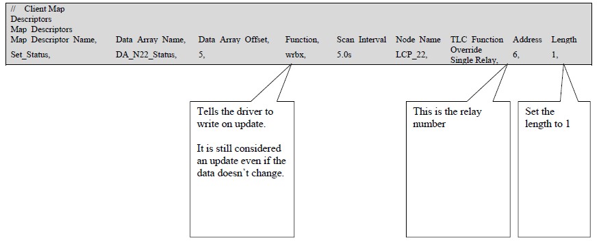
4.10 Map Descriptor (MD) Example 6 – Turning a relay on /off
It is conceivable that you may which to turn relays on / off but not read their status. In such a scenario you cannot use the solutionprovided in example 5. Now you need an MD.
In this example a single MD waits for an upstream node to send data to DA_N22_status offset 5. When the DA location is updated(not necessarily changed) the driver sends a write command to the relay using the 1 or zero found in the DA location to command therelay specified by the 'Address' parameter. Note that the length is 1.
You need one of these MD's for each relay you which to command this way.
4.11 Map Descriptor (MD) Example 7 – Set the Relay Schedule Action
You cannot use the strategy outlined in example 5 to write the Relay Schedule Action because it cannot be read.
In this example a single MD waits for an upstream node to send data to DA_N22_Sched offset 5. When the DA location is updated (notnecessarily changed) the driver sends a write command to the relay using the 1 or zero found in the DA location to command the relayspecified by the 'Address' parameter. Note that the length is 1.
You need one of these MD's for each relay you which to command this way.
Descriptors
Map_Descriptors
Map_Descriptor_Name, Data_Array_Name, Data_Array_Offset, Function, Node_Name TLC_Function Address Length
CMD_N22_Sched6, DA_N22_Sched, 5, wrbx, LCP_22, Schedule Action Single Relay, 6, 1,
4.12 Map Descriptor (MD) Example 8 – Set the Relay Clean Action
Use the same method as in example 7 but change the MD name, DA name and TLC_Function as illustrated below.
Descriptors
Map_Descriptors
Map_Descriptor_Name, Data_Array_Name, Data_Array_Offset, Function, Node_Name TLC_Function Address Length
CMD_N22_Clean6, DA_N22_Clean, 5, wrbx, LCP_22, Clean Action Single Relay, 6, 1,
4.13 Map Descriptor (MD) Example 9 – Set the Relay Shed Action
Use the same method as in example 7 but change the MD name, DA name and TLC_Function as illustrated below.
Descriptors
Map_Descriptors
Map_Descriptor_Name, Data_Array_Name, Data_Array_Offset, Function, Node_Name TLC_Function Address Length
CMD_N22_Shed6, DA_N22_Shed, 5, wrbx, LCP_22, Shed Action Single Relay, 6, 1,
4.14 Map Descriptor (MD) Example 10 – Capturing a PSS Broadcast
PSS switches send broadcast messages when activated. This driver can capture these message and store data from them allowingupstream protocols to read the data and take appropriate actions. If a PSS switch sends a message and the driver cannot find a placeto store the data because there isn't an MD corresponding to the PSS's Node_ID then the message is ignored.
A PSS may have up to 12 switches (Typically there are three switches for each 12 relays on a panel. Thus a LCP48 has 12 switches.The driver stores 5 data values for each switch. . The position in the DA where PSS data is stored is dependent on the switch number.Multiply the switch number by 5 to get the base offset.. Ensure that the Data_Format of the DA is suitable to store integer values.
Base Offset : Src Address Number
Base Offset + 1 : Switch Number
Base Offset + 2 : On/Off, switch state
Base offset + 3 : Initiator
Base offset + 4 : Data Word 0 (raw value extracted from message)
4.15 Map Descriptor (MD) Example 11 – Emulating a PSS
You can have this driver emulate one or more PSS's. Why would you do this ? If you wanted an upstream device to send data whichhas the same effect as a PSS then this provides the solution.
This MD waits for the upstream node to send data which updates the Data Array. When this happens the driver sends a writecommand as if a PSS had been operated.
When the write is triggered the driver extracts 2 consecutive data values from the Data Array. This is despite the fact that the MDlength is 1. Thus you must take care to use the DA correctly and ensure there are no overlaps with other MD's.
The driver extracts the value from offset 0 (in this example) and treats this as the switch number and extracts data from offset 1 andtreats this as the required state. Load the value 17 to have a required state of ON and zero to have the required state of off.
The write is triggers when you update the value (update doesn't mean change) the value at offset zero. So take care to set the requiredstate 1st.
4.16 Map Descriptor (MD) Example 12 – Link Status
Y
If you don't care about the status of the link then don't include this Map Descriptor. Whenever the status of the link changes an unsolicited message is sent you can capture this data with the following Map Descriptor. You can also actively poll for the data bychanging the passive to RDBC. The following data is stored. Contact GE to interpret the data.
Offset 0 : indicates dataline is shorted
Offset 1 : indicates LINK has No Clock
Offset 2 : indicates at least one LAP Relay Failure
Offset 3 : indicates at least one LAP No Program
Offset 4 : indicates that the alarm contacts are closed
Offset 5 : indicates that the unit is a Slave LINK
Offset 6 : Not Used
Offset 7 : means acknowledge alarm button was used to acknowledge alarms (otherwise cleared by computer)
Offset 8 : DF1 & DF2
Offset 9 : DF3 & DF4
Offset 10: DF5 & DF6
Offset 11: DF7 & DF8
Descriptors
Map_Descriptors
Map_Descriptor_Name, Data_Array_Name, Data_Array_Offset, Function, Node_Name TLC_Function Address Length Scan_Interval
Store_LinkStatus, DA_P1_Status, 0, Passive, LCP_22 Link Status, 0, 12, 12.0s
5. Configuring the FieldServer as a GE-TLC Driver Server
A full Server has been implemented. The server implementation allows you configure the FieldServer so that remote devices appear as PSS's and LCP's to the GE system. The server side is used to test the client side as part of an ongoing quality assurance program. If you are interested in using it please contact us.
Appendix A. Advanced Topics
Appendix A.1. Adapter Mode
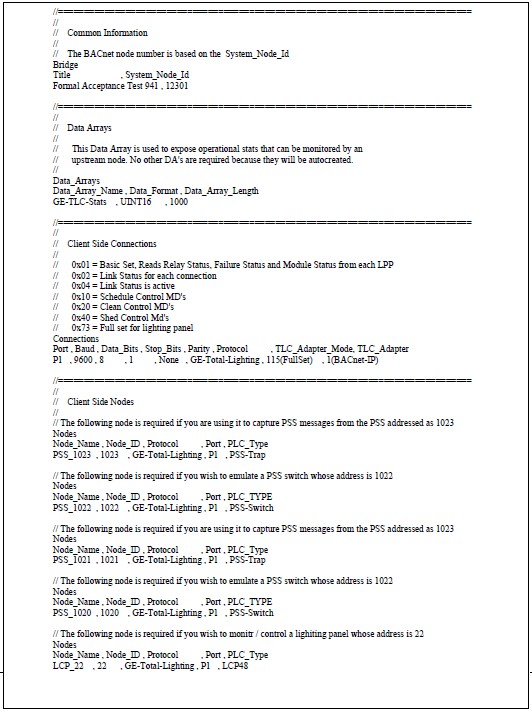
You can configure the driver as an adapter. An adapter reads a predefined set of data from the GE LCP and PSS's and auto creates a server side configuration to provide this data to remote clients using BACnet. The best part of the adapter is that it requires minimal configuration as the driver knows what data to read and what data to serve.
You can choose whether you want the adapter to be BACnet IP or Ethernet.
You can also choose between a number of predefined sets of data.
You can also choose whether the FS creates one BACnet node to server all the data or whether it creates one BACNet node to correspond to each TLC node. (We call these virtual BACNet nodes).
You can exclude a TLC node from auto configuration and configure the node manually by simply assigning a node name that begins with an underscore ('_').
A.1.1 TLC_Adapter
Controls the server protocol and how server nodes are created. The following are permitted settings for this parameter
| Parameter Setting | Notes |
| 1(BACnet-IP) | BACnet-IP server is created. One BACnet node represents all the TLC devices. |
| 2(BACnet-Eth) | BACnet-Ethernet server is created. One BACnet node represents all the TLC devices. |
| 3(BACnet-VIP) | BACnet-IP server is created. One BACnet node is created for each TLC node. |
| 4(BACnet-VEth) | BACnet-IP server is created. One BACnet node is created for each TLC node. |
A.1.2 TLC_Adapter_Mode
Controls the auto-creation of client side Map Descriptors. Depending on the setting the driver will create MD that read different subsets of data from the TLC device. You can use combinations of these subsets.
| Parameter Setting | Notes |
| 1(Basic Set) | Basic Set, Reads Relay Status, Failure Status and Module Status from each LPP |
| 2(Passive Link Status) | Link Status for each connection. Creates MD's to listen passively for Link Status messages. |
| 4(Active Link Status) | Link Status for each connection. Creates MD's to poll for link status data. |
| 16(Schedule Control) | Creates MD's which allow you to send messages to activate/deactivate schedule control. Creates one MD for each relay on the LCP. |
| 32(Clean Control) | Creates MD's which allow you to send messages to activate/deactivate cleaning control. Creates one MD for each relay on the LCP. |
| 64(Shed Control) | Creates MD's which allow you to send messages to activate/deactivate Shed control. Creates one MD for each relay on the LCP. |
| 115(Full Set) | This is a combination arrived at by adding options 1,2,16,32,64. |
A.1.3 BACnet Node_Id's
Non Virtual Node Servers (TLC_Adapter = 1 or 2 )
If you specify a System_Node_Id in your configuration file then the driver will use that to number the BACnet node created to serve the data. If the driver cannot find this setting then it uses a hard-coded number = 11221.
For limitations on the BACnet Node Id read one of FieldServers's BACnet-IP manual.
Example of how to set the System_Node_Id
Title System_Node_Id
Gateway1, 12345,
Virtual Node Servers (TLC_Adapter = 3 or 4 )
The driver attempts to number each BACnet node based on the TLC Node in the following way; The driver looks for the parameter called 'Alias_Node_ID' on the TLC node description. If it finds this parameter then it uses this value as the number of the corresponding BACnet node. If the parameter isn't found then the driver number the BACnet node with the same Node_ID as the TLC node.
A.1.4 BACnet Object ID's
The driver numbers the object sequentially starting at 1 for Virtual Node Servers.
For non-Virtual Node servers the objects are numbered to indicate the type of device and the they are numbered so object representing one node can easily be isolated from objects representing another node. For each new node the 1000 is added to the object ID. If the objects represent a PSS emulation they start at 250, if the objects represent a PSS message trap then they start at 260, if the objects link status they start at 350 and if the objects represent the relays and module they start at 1.
Appendix A.2. Example Adapter configuration file
Appendix A.3. BACnet Object List
A.3.1 Lighting Panel Objects
| # | Object Name (see Note 7) | Obj. ID | Obj Type | Created (See Note 9) | Notes |
| Relay | |||||
| # | Relay Status | ||||
| 1 | Srv_x_RelayStatus1 | 1 | BO | 1 | 1,2 |
| 2 | Srv_x_RelayStatus2 | 2 | BO | 1 | 1,2 |
| 3 | Srv_x_RelayStatus3 | 3 | BO | 1 | 1,2 |
| … | … | … | … | 1 | 1,2 |
| 12 | Srv_x_RelayStatus12 | 12 | BO | 1 | 1,2 |
| … | … | … | … | 1 | 1,3 |
| 48 | Srv_x_RelayStatus48 | 48 | BO | 1 | 1,3 |
| # | Object Name (see Note 7) | Obj. ID | Obj Type | Created (See Note 9) | Notes |
| Relay | |||||
| # | Relay Failures | ||||
| 1 | Srv_x_RelayFails1 | 1 | BI | 1 | 2 |
| 2 | Srv_x_RelayFails2 | 2 | BI | 1 | 2 |
| 3 | Srv_x_RelayFails3 | 3 | BI | 1 | 2 |
| … | … | … | … | 1 | 2 |
| 12 | Srv_x_RelayFails12 | 12 | BI | 1 | 2 |
| … | … | … | … | 1 | 3 |
| 48 | Srv_x_RelayFails48 | 48 | BI | 1 | 3 |
| # | Object Name (see Note 7) | Obj. ID | Obj Type | Created (See Note 9) | Notes | |
| Data Pnt | ||||||
| # | LPP (module) status | |||||
| 1 | Srv_x_ModStatus1 | 49 | BI | 1 | 2 | Clock set if=1 |
| 2 | Srv_x_ModStatus2 | 50 | BI | 1 | 2 | Program set if=l |
| 3 | Srv_x_ModStatus3 | 51 | BI | 1 | 2 | Relay failure if=1 |
| 4 | Srv_x_ModStatus4 | 52 | BI | 1 | 2 | Not defined |
| 5 | Srv_x_ModStatus5 | 53 | BI | 1 | 2 | If = 1 then driver 1 is in place (relay 1-12) |
| 6 | Srv_x_ModStatus6 | 54 | BI | 1 | 2 | If = 1 then driver 2 is in place (relay 13-24) |
| 7 | Srv_x_ModStatus7 | 55 | BI | 1 | 2 | If = 1 then driver 3 is in place (relay 25-36) |
| 8 | Srv_x_ModStatus8 | 56 | BI | 1 | 2 | If = 1 then driver 4 is in place (relay 37-48) |
| 9 | Srv_x_ModStatus9 | 57 | BI | 1 | 2 | Not defined |
| 10 | Srv_x_ModStatus10 | 58 | BI | 1 | 2 | Not defined |
| # | Object Name (see Note 7) | Obj. ID | Obj Type | Created (See Note 9) | Notes | |
| Data Pnt | ||||||
| # | Link Status | |||||
| 1 | Srv_y_ModStatus1 | 350 | BI | 2 | 4 | If set indicates dataline is shorted |
| 2 | Srv_y_ModStatus2 | 351 | BI | 2 | 4 | If set indicates LINK has No Clock |
| 3 | Srv_y_ModStatus3 | 352 | BI | 2 | 4 | If set indicates at least one LAP Relay Failure |
| 4 | Srv_y_ModStatus4 | 353 | BI | 2 | 4 | If set indicates at least one LAP No Program |
| 5 | Srv_y_ModStatus5 | 354 | BI | 2 | 4 | If set indicates that the alarm contacts are closed |
| 6 | Srv_y_ModStatus6 | 355 | BI | 2 | 4 | If set indicates that the unit is a Slave LINK |
| 7 | Srv_y_ModStatus7 | 356 | BI | 2 | 4 | Not defined |
| 8 | Srv_y_ModStatus8 | 357 | BI | 2 | 4 | If set means acknowledge alarm button was used to acknowledge alarms (otherwise, cleared by computer) |
| 9 | Srv_y_ModStatus9 | 358 | AI | 2 | 4 | Time |
| 10 | Srv_y_ModStatus10 | 359 | AI | 2 | 4 | Time |
| 11 | Srv_y_ModStatus11 | 360 | AI | 2 | 4 | Q Length: Incoming |
| 12 | Srv_y_ModStatus12 | 361 | AI | 2 | 4 | Q Length: Outgoing |
| # | Object Name (see Note 7) | Obj. ID | Obj Type | Created (See Note 9) | Notes |
| Relay | |||||
| # | Relay_Schedule | ||||
| 1 | Srv_x_RelaySched1 | 49 | BO | 16 | 8,2 |
| 2 | Srv_x_RelaySched2 | 50 | BO | 16 | 8,2 |
| 3 | Srv_x_RelaySched3 | 51 | BO | 16 | 8,2 |
| … | … | … | … | 16 | 8,2 |
| 12 | Srv_x_RelaySched12 | 60 | BO | 16 | 8,2 |
| … | … | … | … | 16 | 8,3 |
| 48 | Srv_x_RelaySched48 | 96 | BO | 16 | 8,3 |
| # | Object Name (see Note 7) | Obj. ID | Obj Type | Created (See Note 9) | Notes |
| Relay | |||||
| # | Relay_Clean | ||||
| 1 | Srv_x_RelaySched1 | 97 | BO | 32 | 8,2 |
| 2 | Srv_x_RelaySched2 | 98 | BO | 32 | 8,2 |
| 3 | Srv_x_RelaySched3 | 99 | BO | 32 | 8,2 |
| … | … | … | … | 32 | 8,2 |
| 12 | Srv_x_RelaySched12 | 108 | BO | 32 | 8,2 |
| … | … | … | … | 32 | 8,3 |
| 48 | Srv_x_RelaySched48 | 144 | BO | 32 | 8,3 |
| # | Object Name (see Note 7) | Obj. ID | Obj Type | Created (See Note 9) | Notes |
| Relay | |||||
| # | Relay_Shed | ||||
| 1 | Srv_x_RelaySched1 | 145 | BO | 64 | 8,2 |
| 2 | Srv_x_RelaySched2 | 146 | BO | 64 | 8,2 |
| 3 | Srv_x_RelaySched3 | 147 | BO | 64 | 8,2 |
| … | … | … | … | 64 | 8,2 |
| 12 | Srv_x_RelaySched12 | 156 | BO | 64 | 8,2 |
| … | … | … | … | 64 | 8,3 |
| 48 | Srv_x_RelaySched48 | 192 | BO | 64 | 8,3 |
A.3.2 PSS Objects
PSS Traps
(A PSS Trap is a way of monitoring a remote PSS switch so that its activation can be monitored by an upstream front end)
| # | Object Name (see Note 7) | Obj. ID | Obj Type | Created (See Note 9) | Notes | |
| 1 | Srv_PSSz_Trap1 | 260 | AI | 10 | Switch 0: PSS Switch Address | |
| 2 | Srv_PSSz_Trap2 | 261 | AI | 10 | Switch 0:PSS Switch Number | |
| 3 | Srv_PSSz_Trap3 | 262 | BI | 10 | Switch 0:On/Off State | |
| 4 | Srv_PSSz_Trap4 | 263 | BI | 10 | Switch 0:Initiator | |
| 5 | Srv_PSSz_Trap5 | 264 | AI | 10 | Switch 0:Df0 | |
| 6 | Srv_PSSz_Trap6 | 265 | AI | 10 | Switch 1: PSS Switch Address | |
| 7 | Srv_PSSz_Trap7 | 266 | AI | 10 | Switch 1:PSS Switch Number | |
| 8 | Srv_PSSz_Trap8 | 267 | BI | 10 | Switch 1:On/Off State | |
| 9 | Srv_PSSz_Trap9 | 268 | AI | 10 | Switch 1:Initiator | |
| 10 | Srv_PSSz_Trap10 | 269 | AI | 10 | Switch 1:Df0 |
PSS Emulation
(A PSS emulator is a way of emulating a PSS switch. When the upstream remote front end sends data to these objects, a message is sent on the TLC network as if a PSS had been activated)
| # | Object Name (see Note 7) | Obj. ID | Obj Type | Created (See Note 9) | Notes | |
| Relay | ||||||
| # | Relay_Shed | |||||
| 1 | Srv_PSSz_Emulate1 | 250 | AO | 11 | Module # | |
| 2 | Srv_PSSz_Emulate2 | 251 | AO | 11 | PSS # | |
| 3 | Srv_PSSz_Emulate3 | 252 | BO | 11 | On/Off State |
A.3.3 Notes to the Object List
| Note Number | Notes |
| 1 | Remote BACnet front end can write to these points. Set point on to have adapter send on command to relay. Set the point off to turn relay off. |
| 2 | Objects are only created for Lighting Panels |
| 3 | Objects are only created for Lighting Panels with 48 |
| 4 | Objects are created for each connection/link |
| 5 | Objects are only created for PSS Switch Emulators |
| 6 | Objects are only created for PSS Switch Traps |
| 7 | 'x' is the number(address) of the Lighting Panel client node. Typically LPP22 for lighting panel #22'y' is the number of the link. Depends on FieldServer port number |
| 8 | Remote BACnet front end can write to these points. Set point on to have adapter activate indicated command. Set point off to deactivate indicated command. |
| 9 | These Objects are created depending on the Adapter_Mode value. Thus the adapter may be configured to create/not create various sets of objects |
| 10 | Each PSS has more than one switch. There are 5 objects per switch, |
| 11 | Always update object 251, 252 and only then 250. It is the update of object 250 that send the message |
Appendix B. Troubleshooting tips
Appendix B.1. Connection Tips & Hints
Forcing a link reset.
Section Appendix B.3 provides information on how to expose driver stats. Once configured, you can poke values into the Data Array where the stats are reported to generate a reset of link by
Appendix B.2. Driver Error and Warning Messages
A number of corrective actions require that you edit the configuration file. When you have completed the edit, you must download the modified configuration file to the FieldServer and reset the FieldServer for the changes to take effect.*
| Error Message | Meaning and Corrective Action |
| TLC:#1 Err. TLC_Function=%#x is unknown | The driver prints this message if it cannot perform the task required. Please review your configuration checking that the parameter 'TLC_Function' has been specified correctly. If you are happy with the config then please take a log and contact Tech Support. |
| TLC:#2 FYI PSS Switch Message ignored. | A message was received from a PSS but theconfiguration does not contain a matching PSS node and thus the driver could not store the contents of the message. This is normal – not all configurations are interested in monitoring all PSS's. The driver prints the message one and then suppresses it to catch your attention and to suggest that you may wish to check you configuration. |
| TLC:#3 FYI PSS message rcvd and stored. No action taken. | This is just a warning to remind you that the FieldServer is not a TLC lighting control panel and cannot execute any actions when a PSS message is received. The driver prints the message one and then suppresses it to catch your attention and to suggest that you may wish to check you configuration. |
| TLC:#3 FYI Diagnostic 1/2/3/4/5 | An internal diagnostic has been generated. This is abnormal. Please take a log and contact tech support. |
| TLC:#4 Err. DA=%s too short. Rqd=%dAct=%d | The driver is trying to store data but found that the Data Array indicated in the message is too short. This occurred while storing PSS Data. The required length is indicated in the message. Edit the configuration, change the length of the Data Array, you may need to change the length of the Map Descriptor too. * |
| TLC:#05 Err. DA=%s too short. Rqd=%d | See message #4.This message is printed while storing unsolicited relay status or relay failure data. |
| TLC:#06 Err. DA=%s too short. Rqd=%d Act=%d | See message #4This message is printed while storing unsolicited module status data. |
| TLC:#07 Err. DA=%s too short. Rqd=%d Act=%d | See message #4This message is printed while storing unsolicited link status data. |
| GE_TLC:#08 Err. Can't Write through except 'Relay Status' | An upstream device has written to a point in a Data Array that corresponds to data being read from a TLC node. If the data being read is the relay status data then that is ok.- the driver will send a message to turn the corresponding relay on/off ( see section 4.9) However, if the data point represents any other data the driver does not know what to do with this data and must abandon it. In such cases this message is printed. The only corrective action that can be taken is to ensure that upstream clients only write to appropriate Data Array locations.
If this error occurs repeatedly then you need to take an Ethernet log of the BACnet communications as well as a FieldServer log and contact Tech Support.
An Ethernet log is taken using the Ethereal package. Read Enote ???? on the FieldServer website for more information on how to do this. |
| TLC:#09 Err. Client Timeout. Reconnection Rqd. | A message was sent to the R-Link but no response was received in the timeout period. The timeout is adjustable. Set the timeout on the connection to a larger value. *
The other corrective action you can take other than is to check the physical connection and the state of the R-Link device. |
| TLC:#10 Err. Rqst Type=%x is unknown for cmd=0x14 | Please take a log and contact tech support. |
| TLC:#11 Err. Msg Func=%#x is unknown | The server is parsing a poll from the client side of the driver. Take a log and contact Tech Support. |
| TLC:#12 Err. Rqst Type=%x is unknown for cmd=0x14 | A response or unsolicited message from the R-Link cannot be parsed correctly because the driver does not know how to interpret it. Take a log, ensure that the log is running while one of these message is printed. Then contact Tech Support. |
| TLC:#13 Err. Msg Func=%#x is unkown | See msg #12 |
| TLC:#15 Err. DA=%s too short. Rqd=%d | The server is trying to build a response. During the process it tried to get data from a Data array point that doesn't exsit. The required length and the DA name are indicated in the message. Edit the config and increase the DA length. Sometimes you may need to increase the length of the MD using the DA. * This message is printed while a response is being built to a command to set a really, schedule a relay, clean or shed a relay |
| TLC:#16 Err. DA=%s too short. Rqd=%d | See the notes for msg #15. This message is printed while a response is being built to a request for relay status or relay fail status. |
| TLC:#17 Err. DA=%s too short. Rqd=%d Act=%d | See the notes for msg #15. This message is printed while a response is being built to a request for module status. |
| TLC:#18 Err. DA=%s too short. Rqd=%d Act=%d | See the notes for msg #15. This message is printed while a response is being built to a request for link status. |
| TLC:#19 Err. Rqst Type=%x is unknown for cmd=0x14 | A request for data poll requested a set of data with a function code that the server does not recognize. Take a log, ensure that the log is running while one of these message is printed. Then contact Tech Support. |
| TLC:#20a FYI Autoconfigure as Adapter begins … | No corrective action is required. When the driver starts the process of building the adapter (see section Appendix A.1) this message is printed. |
| TLC:#21 Err. DA=%s too small. Rqd=%d | The driver is storing data from a poll response. The indicated Data Array is too small. You will need to edit the config and change the length of the Data Array Sometimes you may need to increase the length of the MD using the DA. * This particular message is printed when the driver is storing data from a message used to set a relay state. |
| TLC:#22 Err. DA=%s too small. Rqd=%d Act=%d | See msg#21. This particular message is printed when the driver is storing data from a PSS broadcast message. |
| TLC:#23? Err. DA=%s too small. Rqd=%d Act=%d | See msg#21. This particular message is printed when the driver is storing data from a relay status or relay fail state message. |
| TLC:#24 Err. DA=%s too small. Rqd=%d Act=%d | See msg#21. This particular message is printed when the driver is storing data from a module status message. |
| TLC:#25 Err. DA=%s too small. Rqd=%d | See msg#21. This particular message is printed when the driver is storing data from a link status message. |
| TLC:#26 Err. Checksum calc. Num bytes=%d | Driver found that a message had an odd number of bytes. Take a log. If possible generate the situation that caused the message to be printed again during the log. Then call tech Support. |
| TLC:#27 Err. Node=%s. Equip. Type not specified. | You must correct the configuration* Please specify the PLC_Type parameter for each node. Select from the settings listed in section 4.3 |
| TLC:#28 Err. Node=%s. Equip. type not recognized. | You must correct the configuration* The equipment type specified with the PLC_Type parameter was not recognized. Select from the settings listed in section 4.3 |
| TLC:#29 Err. Bad Node_ID=%d Max=1024. Default to 1 | The max permitted Node_ID for a TLC node is 1024. You must correct the configuration* |
| TLC:#30 Err. Bad Length. Defaulting to 1 | A length should be specified. Eliminate this error by correcting the configuration file. * |
| TLC:#31 Err. TLC_Function must be specified. | You must correct the configuration* Please review the example MD's starting in section 4.5 |
| TLC:#32 FYI Port Handle=%d | No corrective action is required. You use the handle to calculate an offset into the exposed stats Data Array. See Appendix B.3 |
| GE_TLC:#33 FYI. Link Reset Requested. | No corrective action is required. This message is printed each a non-zero value is poked into the exposed stats Data Array and the driver recognizes the non-zero value as a trigger to rest the link. |
| TLC:#34 Err. There are no TLC Devices. | The driver was configured for Auto Configuration but there were no GE-TLC devices (Nodes) in the configuration file. These form the basis for the auto configuration. Read the chapter Appendix A.1, then edit the configuration file. Download the modified config file to the FieldServer and then reset the FieldServer to give effect to the changes. |
| TLC:#35 FYI. Tunnel enabled. | The driver has been configured to act as a tunnel for a TLC configuration computer. Read Chapter Appendix C for more information. This message is printed for your information only. If it confirms a behavior you expected then ignore the message. |
| TLC:#36 FYI. Tunnel inhibited. Read Manual for use. | The driver has been not configured to act as a tunnel for a TLC configuration computer. This is normal. The message has been printed to draw your attention to the functionality described in Appendix C . You may safely ignore this message. |
| TLC:#37 Err. One BACnet Node required. | For Autoconfigiration only one BACnet node may be defined in the configuration file. Read Appendix A.2 for an example configuration file. Now edit your configuration file, download the modified file and reset the FieldServer for the changes to take effect. |
| TLC:38b Err. MD Name too long | Take a log and call Tech Support. |
| TLC:#39a Err. Heading not equal to keywords | Take a log and call Tech Support. |
| TLC:#40 FYI No auto config for node=%s | If a node name begins with a '_" (Underscore) then the driver will not include that node in the auto configuration task. The driver assumes that the Map Descriptors to read/serve data for theat node are configured manually. |
| TLC:#41 FYI Bridge_ID not set. Used for BACnet Node. | The driver needs to set the BACnet Device ID (Address). To do this a 'System_Node_Id" must be set as a bridge parameter. If not specified the driver uses a hard coded ID=11221. Read Appendix A.2 for an example of how to do this in the configuration file. Now edit your configuration file, download the modified file and reset the FieldServer for the changes to take effect. |
| TLC:#42 FYI. DLL starts connection seq. TLC:#42b FYI. Waiting for Rlink Baud Rate Sensing …..
TLC:#42d FYI. Connecting …..
TLC:#42c FYI. Connected ! | The messages are printed during the connection sequence. They are normal and may safely be ignored. |
| TLC:#43 Err. Could not connect to Rlink. | The driver timed out waiting for the Rlink to start the connection sequence. Check the connection and connection settings. Perhaps the Baud, parity … are incorrect. |
| TLC:#44 Err. Buffer Overflow. | The in buffer overflowed during an attempt to connect. This typically happens when the connection settings are incorrect. Check the baud, parity …. If you are convinced that the settings are correct take a log. Inspect the log, the messages should be human readable. If they are not then the connection is not correct, or something is injecting noise on the line. Check you connection again. If the log looks valid contact Tech support. |
| TLC:#45 FYI. Timeout waiting for 'LINK' message. | The driver timed out waiting for the Rlink to start the connection sequence. Check the connection and connection settings. Perhaps the Baud, parity … are incorrect. |
| TLC:#46 Err. Timeout waiting for response. | The driver timed out waiting for a response from a poll. Check the connection. If the message is printed occasionally it is probably an intermittent error caused by an occasional corrupted message. If it occurs often then take a log and contact tech support. (If you are taking the log manual then be sure to capture the byte timing too –Zp1[t] is a typical command line parameter for the log). |
| TLC:#47a Err. Bad byte/chksm in msg from tunnel. Ignored TLC:#47b FYI Ignored NAK from tunnel
TLC:#47c FYI Ignored ACK from tunnel | You can safely ignore these messages unless they are printed frequently – in such cases it may indicate that the connection setting such as baud rate for the secondary port are incorrect. The driver prints these errors when it receives a message from the configuration PC that have errors in them, They are not copied to the Rlink port. |
| TLC:#48 Rcvd from tunnel | You can safely ignore this message. It is a copy of the message sent by the configuration PC to the secondary port. |
| TLC:#49 START+3 response to tunnel | The driver has received an unexpected message. This is not necessarily and error. If you are concerned then please take a log, try to reproduce the event which caused this message. If you send the logs to tech Support. |
| TLC:#50 FYI Busy with tunnel, delaying poll. | The driver prints this message when it receives a message from the configuration PC on the secondary port. It copies the message to the primary port and suspends it own polling activity for a period. You can safely ignore this message. Read section 4.2 for more information. |
| TLC:#51 FYI Tunnel idle timer=%ld milliseconds | You can safely ignore this message if it confirms your expectation. The driver this message to report how long it suspends polling for when a message is received on the secondary port. The message is printed once and suppressed. |
| TLC:#55 FYI. Send Tunnel Client Connection Response." | This message is printed to report that a request for a connection was sent to the tunnel and the driver responded to allow to remote PC software to think it is connected to the TLC network. That is fine provided that the FieldServer has managed to establish its connection to the Rlink. |
| TLC:#56 FYI. This device will respond to polls. | The connection has been configured to respond to polls from a remote client. That is normal if the FieldServer is configured as a server (ie. Has been configured to emulate some lighting panels). However, this will be a problem if the driver has been configured as a client – it will not know how to respond to the polls. Please read section 3.5.1 for more information. |
| TLC:#57 FYI. This device will ignore to polls. | The connection has been configured to ignore to polls from a remote client. That is normal if the FieldServer is configured as a client (ie. Has been configured to read data from the lighting panels). However, this will not be a problem if the driver has been configured as a server – it will know how to respond to the polls. Please read section 3.5.1 for more information. |
| TLC:#58 FYI. DLL forced to retry connection seq. | You can safely ignore this message. It is printed to aid Tech Support. |
Appendix B.3. Driver Stats – How an Upstream Device can Monitor Performance.
If this driver is appropriately configured , it can expose operation statistics in a Data Array which can be monitored by a remote device to check that the driver is performing without error.
The lines from the example below can be cut and pasted into a configuration file to expose these stats.
Data_Array_Name, Data_Format, Data_Array_Length,
GE-TLC-Stats, UINT32, 1000,
The driver maintains one set of stats for each communication port.
To determine the base offset use the following formula:
Base Offset = Port Number * 100 where Port Number is the port number printed in the error log by message #32.
Relative Offset : Calculate the offset of each stat by adding the relative offset to the base offset.
| Relative Offset | Description | |
| 1 | Each time client side queue's message for channel idle. Normally equal to the number of Polls sent. | |
| 2 | Increments by message length each time client side queue's message for channel idle. Normally equal to the number of Poll bytes sent. | |
| 3 | Increments by 1 each time client side queue's a read message | |
| 4 | Increments by 1 each time client side queue's a write message | |
| 5 | Increments by 1 each time client poll messages are sent to port. | |
| 6 | Increments by message length each time client poll message is sent to the port. | |
| 7 | Increments by 1 each time that the channel buffer overflows. Probably means wrong connection settings or wrong device. | |
| 8 | Increments by 1 each time a message has invalid (non-ASCII) bytes | |
| 9 | Increments by 1 each time a message has invalid checksum | |
| 10 | Increments by 1 each time a non-special message is rcvd and the driver cannot determine the message direction | |
| 11 | Increments by 1 each time a message is determined to have come from the client | |
| 12 | Increments by 1 each time a message is determined to have come from the server | |
| 13 | Increments by 1 each time the channel sends an ACK | |
| 14 | Increments by 1 each time the channel receives a DOT message | |
| 15 | Increments by 1 each time the channel receives a DOT message that says '.HANDSHAKE' | |
| 16 | Increments by 1 each time the channel receives a DOT message that says '.NOHANDSHAKE' | |
| 17 | Increments by 1 each time the channel receives a DOT message that says '.BAUD' | |
| 18 | Increments by 1 each time an unexpected message is received while trying to connect | |
| 19 | Increments by 1 each time an a connection is made with the RLINK | |
| 20 | Future use | |
| 21 | Increments by 1 each time an ACK is received from the downstream device | |
| 22 | Increments by 1 each time an NAK is received from the downstream device | |
| 23 | Increments by 1 each time an empty message is received | |
| 24 | Increments by 1 each time a DOT message is received | |
| 25 | Increments by 1 each time a message that has no errors in its format, isn't an ACK, NAK or dot message | |
| 26 | Increments by 1 each time the data link layer has a timeout | |
| 27 | DTR Line. Each side can set this to toggle the DTR line. When you da_put you set DTR. When you da_get you get DSR. This stat is always set at absolute offset 27. That is, the offset is not dependent on the port. | |
| 28 | DTS Line. Tied to DCD line according to their docs) This stat is always set at absolute offset 28. That is, the offset is not dependent on the port. | |
| 29 | Poke the value 1 into this location and the client will try and reset the link when the next poll is sent. | |
| 30 | Increments by 1 each time driver is doing auto config and finds a node begin with '_' and skips auto config for the node | |
| 31 | Increments by 1 each time driver receives a complete valid message on the tunnel port from the tunneling device | |
| 32 | Increments by 1 each time driver receives an invalid message (checksum, bad preamble, format or invalid length) on the tunnel port from the tunneling device | |
| 33 | Increments by 1 each time drivers tunnel in_buffer overflows. This usually means that that the driver is not sending the messages out the primary port. | |
| 34 | Increments by 1 each time the inter byte time on the tunnel receive buffer is too large. The in_buffer is cleared. | |
| 35 | Set to 1 to have tunnel debugging print messages on the driver screen, | |
| 36 | Increments by 1 each time driver receives a byte on the tunnel port from the tunneling device | |
| 37 | Set to 1 to bypass connection sequence | |
| 38 | Each time a NAK is passed from the dll to the client layer and is then ignored. Nak's could come in response to other RLINK's messages. |
Appendix B.4. Node Offline
The driver follows the standard FieldServer procedures for offline node with one exception – If all the nodes on a connection are offline the driver will reset the link with the Rlink.
The notes below may be superseded by the Bridge Configuration manual as they describe the general functionality of the FieldServer.
Normally, the driver tries each node 3 times (Node parameter = Retries). It waits 10 seconds (Node parameter = Retry_Interval) between retries. Thereafter it puts the node status to offline and waits 30 seconds before retrying (Node parameter = Recovery_Interval) until it receives a good response. The normal polling interval is specified by the Map Descriptor parameter = Scan_Interval. Good polls must continue for a period of 2 seconds before the driver puts the node back online. This period is controlled by the Node Parameter = Probation_Delay
When a node is offline or when the data read by the client side of the driver has aged out the server side of the driver stops serving the data. You can control the data age aspect of behavior using the Bridge parameter = Cache_Age_Limit whose default value is 300 seconds. The offline behavior can be controlled by the node parameter = Srv_Offline_Method . The following are permitted values for this parameter.
Ignore_Clients =synonym= Always_Respond
Any_Offline
All_Offline,
Don't forget that this parameter is applied to the Server Node Descriptors to give the following effect – When a remote client polls for data the FieldServer inspects the data status before responding. If the data is 'offline' then the response is based on the setting of the parameter. One server node may be serving data read from several lighting panels/ devices.
Appendix C. Configuration as a Tunnel
Appendix C.1. Simultaneous support for a Configuration PC
The driver can allow a computer running the GE TLC Configuration application to send messages to the TLC network using the same Rlink. The computer is connected to a secondary port. Every message the computer sends is copied to the Rlink port and every respond from the Rlink is copied back to the secondary port. When the secondary port is active receiving a message from the configuration PC, the driver suspends its own polling for a short period. The period can be configured.
This solution saves the requirement for a second Rlink device to be installed. The purpose of this functionality is to allow for occasional monitoring and configuration changes. It is not intended to provide support for a continuously polling remote device.
This configuration has been tested by GE TLC's tech support group.
Appendix C.2. Limitations of the tunnel
The tunnel in the driver has been designed to allow upload/download of configuration without using PC software without requiring an extra Rlink. It is expected that this occurs infrequently and as a maintenance task. It was not designed to allow the tunnel to be used for continuous data configuration or status or command data transfer. It is expected that during the upload / download that remote operation of relays using the FieldServer will not occur. If they do occur it is possible that some of these commands will be lost. There are two parameters used to control the tunnel. These can be used to experiment to find the optimal setting for your site but performance is not guaranteed. If you require reliable remote control of the relays using the FieldServer do not leave the software using the tunnel to remain running and continuously polling the network and further, use the tunnel to transfer configurations only when this remote operation is not required. If these limitations are not acceptable to you then do not use the tunnel.
During testing it was found that a highly satisfactory performance could be achieved with the tunnel. Results may vary.
Appendix C.3. Block Diagram for Tunnel Configurations
Block Diagram of a FieldServer providing a tunnel to allow simultaneous configuration and monitoring using a PC running GE-TLC configuration software.
Appendix C.4. Cable for Secondary Port (Tunnel) Connection (FS20 and FS40)
Appendix C.5. Cable for Secondary Port (Tunnel) Connection (FS30 Series)
Appendix C.6. Tunnel Trouble Shooting
C.6.1 Baud Rate and connection settings:
The Baud rate of the tunnel connection is fixed by the baud rate of the primary connection. Thus if the baud rate of your primary connection is 9600 then the tunnel expects messages at the same baud rate. This applies to the other connection settings such as parity, stop_bits and data_bits.
Check that baud rate of the GE Software or WinControl is set at the same baud rate. If you are using Remote Serial Port devices such a Lantronics RSP then ensure that its baud rate is set the to the same value.
We have had one customer report, that once the Windows software had tried to connect at 19200, then the RSP device which auto sensed the baud rate, remained at 19200 despite changes to the windows software.
C.6.2 Do not keep the tunnel active all the time:
If the windows software is permanat3ently sending messages to check the status of the lighting panels then the tunnel will be active all the time and the FieldServer will not have time to do its work of polling for data. Read about 'TLC_Tunnel_Delay' in section 4.2
C.6.3 TLC_Tunnel_Delay Settings:
TLC_Tunnel_Delay=10msec Tunnel_Option=0(Default):
During testing, a value of 10 with Tunnel_Option=0(Default), was found to allow upstream devices to control relays with satisfactory but not perfect performance while WinControl continuously monitored the panel. Uploading / Downloading a configuration with Wincontrol and simultaneously controlling relays through the FieldServer was not tested.
TLC_Tunnel_Delay=500msec Tunnel_Option=1:
During testing, a value of 10 with Tunnel_Option=1, was found to allow upstream devices to control relays with highly satisfactory but not perfect performance while WinControl continuously monitored the panel. Uploading / Downloading a configuration with Wincontrol and simultaneously controlling relays through the FieldServer was not tested.
6. Revision History
| Date | Resp | Format | Driver Ver. | Doc. Rev. | Comment |
| 12/11/04 | PMC | PMC | 0.00 | 0 | Created |
| 06/19/05 | PMC | PMC | 1.00a | 0 | Updated after GE testing. |
| 07/12/05 | PMC | PMC | 1.00a | 1 | Minor Corrections. |
| 10/17/05 | PMC | PMC | 1.00a | 2 | Added LCP24 |
| 12/28/05 | PMC | PMC | 1.01h | 0 | Tunnel connection for FS30 Series. |
| 02/13/06 | PMC | PMC | 1 | Example for PSS emulation previously referred to three elements required to complete the action. This has been corrected to refer to 2. | |
| 03/04/06 | PMC | PMC | 1.00m | 0 | More notes on tunnel. Added limitations. Described Tunnel_Mode. |
| 11/27/07 | PMC | PMC | All | 1 | Connection Photo |
| 3/26/08 | PMC | PMC | All | 2 | Rlink connector |
| 8/1/08 | PMC | PMC | All | 3 | Updated connection diagrams and added note about P2 use of FS30. |
