July 2012 Newsletter

site_logo3.gif

CAS Newsletter July 2012

IN THIS ISSUE
  • CAS Change of Address
  • Getting Support from CAS
  • CAS BACnet Explorer New Version Released
  • Utilizing Modbus Scanner to Write Registers of Digitrip 3000 (Protective Relays) Controls
  • Testing An SNMP Configuration
  • Root Mean Square / Effective Value in Electrical Engineering
  • Fire Alarm Device States

CAS Change of Address

Chipkin Automation Systems has moved! Our new address is as follows:

3381 Cambie St., #211Vancouver, BCCanada,V5Z 4R3

Our office telephone number remains unchanged.

Please make note of the above information and direct all correspondence to us at our new address. Thank you.

Getting support from CAS

Recently CAS has added to its team of people providing technical support and we are currently increasing the number of hours per day that we are available for support. Our short term aim is to provide 7am to 5pm coverage for the whole of North America.  We will be providing new support phone numbers soon. We recommend that you send all your emails requiring technical support to [email protected]. Those emails go to the support team and not to an individual will increase our ability to respond promptly and effectively.

The following set of tools can be used to share desktops and help us to provide support more efficiently.

  • Teamviewer
  • Gotomypc
  • Logmein
  • Skype share desktop

Filesanywhere.com  or similar is a good way to send us files that are too large to fit in an email. Its free. Login, upload the file and send us the link.

We always recommend that you call us from the site before you leave so that we can check if you have gathered the diagnostic information and other additional information we need. If you are heading to a site for a new installation, feel free to call us and plan to ensure we have a support engineer available for you while you are on site.

We understand the cost in time and money of repeat site visits. Help us help you minimize these costs by making us part of your planning process.

CAS BACnet Explorer Release of New Version 2.02aA

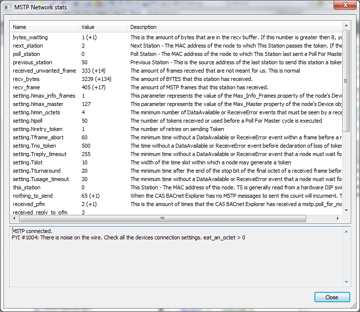
mstp_dialog1.png

Chipkin automation system is releasing a new version of the CAS BACnet Explorer (2.02aA) that dramatically improves the performance of the MSTP network as well as resolving many other bugs. The new version should be available for download .

Updates:

  • Major updates to the MSTP network. The MSTP network will be much faster, use less resources, and more compatible with more devices.
  • Updated to the BACnet API, more compatible with other devices, many bugs resolved in the BACnet API stack.
  • Improved the ability to poll proprietary objects and properties.
  • Bug fixes:
  1. Monitor list no longer sends WhoIs address
  2. Monitor list will continue to poll when minimized.
  3. Fixed bug where writing a boolean values would be interpreted incorrectly.
  4. Fixed bug with WhoIs so that it sends broadcasts correctly.
  5. Many bug fixes to the copy protections system.
  6. Refreshing a single property now will use read property instead of read property multiple.
  7. Fixed spelling mistakes.

Utilizing Modbus Scanner to Write Registers of Digitrip 3000 (Protective Relays) Controls

Introduction

Digitrip 3000 Protective Relays are manufactured by Cutler-Hammer (Eaton Corporation). Typically, Modbus TCP registers are provided as control registers for these Digitrip 3000 Protective Relays in the Digitrip 3000 Control documentation.

It is very important to note that ALL of these Modbus TCP registers which are provided in the above mentioned Digitrip 3000 Control documentation, are Holding registers (Analogue Outputs).

Using Modbus Scanner and Writing the Registers

The following steps should be followed in order to successfully write to the Modbus registers using Modbus Scanner.

1. Opening the Modbus Scanner

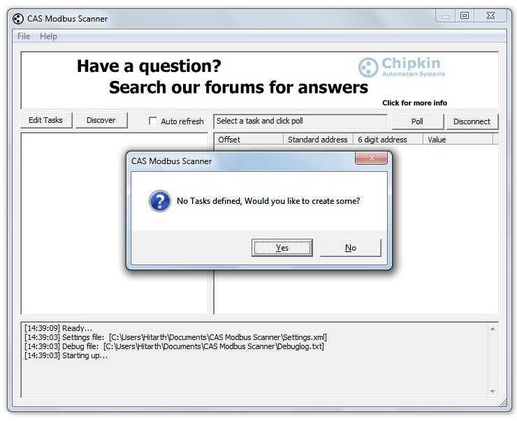
If there are no tasks defined in the scanner, then the first thing asked by the Modbus Scanner on opening is No tasks defined, would you like to create some?. This is shown in the screen shot shown in figure 1 below.

mod1.jpg

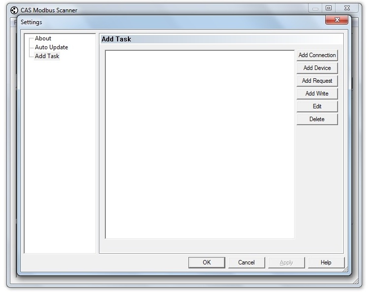
If there are tasks already defined in the system, then just a click is required on Edit Tasks option on the upper left-side of the screen shown in the figure 1, and clicking on Edit Tasks will populate the tasks in the left-side space on the screen. Clicking Yes to the question in the screen shown above, will lead to the settings screen shown in figure 2 (shown below).

mod2.jpg

2. Adding a Connection:

Next step is to add a connection. Clicking on Add Connection tag opens up the following screen (figure 3).

mod3.jpg

Here, the IP Address is the IP Address of the gateway (Field Server) and Port is to be kept 502 (default). Clicking on Add TCP Connection here, adds the connection to the task window.

3. Adding Device:

To add the device, click the Add Device tag on the Settings window. It opens up a dialogue box as shown in figure 4 below.

mod4.jpg

Here, the Slave ID is the ID of the gateway (fieldserver). A click on the Add Device adds the device to the hierarchy in the task window.

4. Adding a Request:

To add Request to the task, click on the Add Request tag on the right-side of the Settings window. It opens up a dialogue box as shown in figure 5 below.

mod5.jpg

Here, it is important to note that ALL of the Modbus TCP registers provided in the Digitrip 3000 Control documentation, are Holding registers (Analogue Outputs). Therefore, as shown in the screen shot above, choose function 03 Read Holding Registers (4xxxx) from the function drop-down box. Offset and length are to be kept according to the details mentioned in the control documentation.

5. Writing to the Modbus Registers:

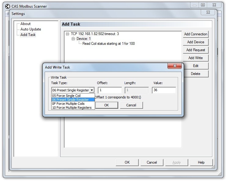
To write to the Modbus registers click Add Write tag in the settings window. It opens up a dialogue box as shown in figure 6 below.

mod6.jpg

Make an appropriate choice from the Task Type drop-down box as shown above. Force Single Coil writes to the single Coil, Force Multiple Coils writes to multiple coils, Preset Single Register writes to the single holding register and Force Multiple Registers writes to multiple registers.

Testing An SNMP Configuration

  1. Configuration is provided at end of file
  2. SNMP driver = 1.03mK
  3. User PowerSNMP Manager download = its free.

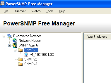
Test by polling for OIDs

Download and install PowerSNMP Free Manager http://www.dart.com/psnet_free.aspx

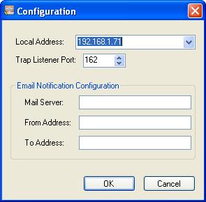
You are presented with this configuration screen when you start the app.

SNMP_Config.jpg 

192.168.1.71 is the IP address of your Laptop

Click OK/Cancel. It doesn't matter.

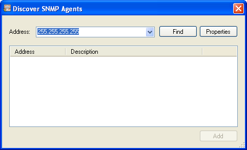
SNMP_Discover.png

Click Discover.

SNMP_IP.png

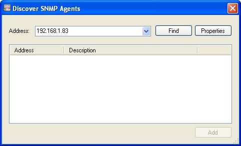
Specify the IP of the Fieldserver/gateway.

SNMP_Find.jpg

Click Find.

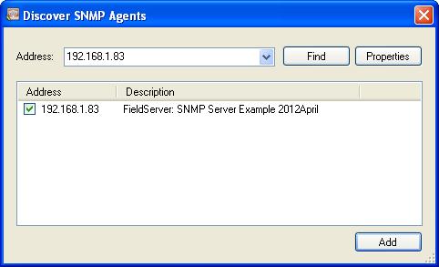
When found looks like below.

SNMP_Agent_Add.png

Check the box.

Click Add.

SNMP_AddResult.jpg

You see the result of the ADD.

SNMP_Add_Watch.png

Right Click on the device and select Add Watch.

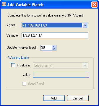
You see this screen. The default variable (OID) is not correct.

SNMP_Variable.png

The variable/OID below corresponds to the 1 st item in DA_SNMP_1.

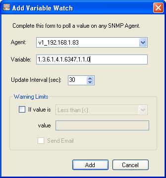
SNMP_Variable2.jpg

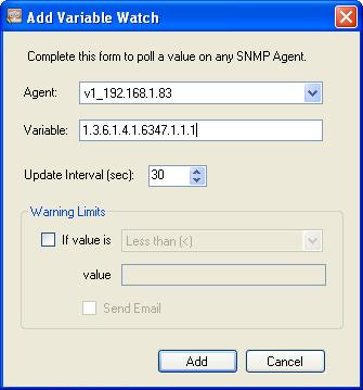
The variable/OID below corresponds to the 2nd t item in DA_SNMP_1.

SNMP_Variable3.jpg

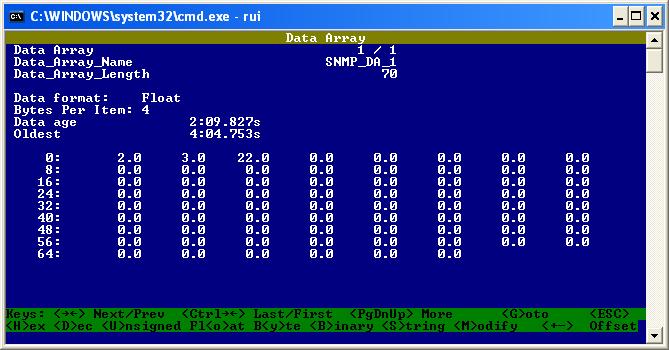
SNMP_RUI.jpg

Here you can see the values.

SNMP_polling.png

Test for polling is complete.

Testing Traps

Make sure IP is the IP of your laptop

Remote_Client_Node_Descriptors

Node_Name , Node_ID , Protocol , Adapter , IP_Address

Mngr1     , 11      , SNMP     , N1      ,  192.168.1.71

Start Wireshark

SNMP_Wireshark.jpg

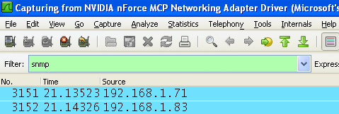
Set the filter to SNMP.

SNMP_Filter.png

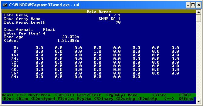
Generate a trap by poking data into offset 11.

Poke the value 1 into offset 11.

SNMP_Trap.jpg

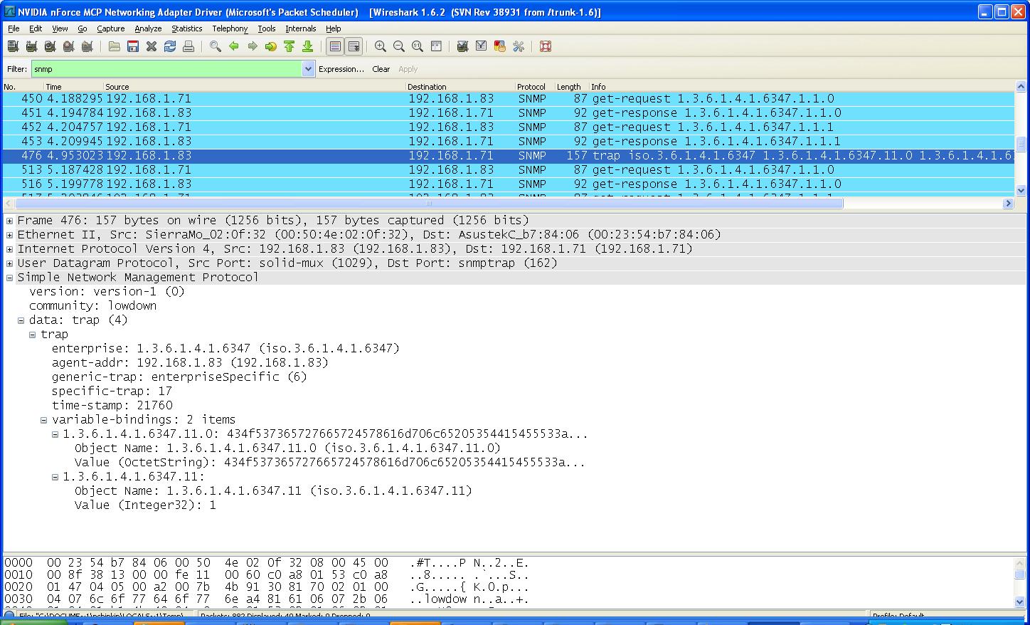
You should see a trap in wireshark.

Expand the trap packt. See the value = 1 . Note the text.

SNMP_Expand_Trap.jpg

Set the value of offset 11 back to zero.

Look for a new trap.

SNMP_New_Trap.jpg

Expanded view of trap.

SNMP_Expand_Trap21.png

Check value is zero.

Set the value of offset 12 to 100.

Set the value of offset 12 to 101.

Set the value of offset 12 to 80.

Set the value of offset 12 to 15.

There should be 3 traps.

SNMP_3_traps.png

Test is complete.

Configuration

//================================================================================

//

//    Common Information

//

Bridge

Title

SNMP Server Example 2012April

//================================================================================

//

//    Data Arrays

//

Data_Arrays

Data_Array_Name , Data_Format , Data_Array_Length

SNMP_DA_1       , FLOAT       , 70

//================================================================================

//

//    Server Side Connections

//

Connections

Adapter , Protocol , SNMP_Community

N1      , SNMP     , lowdown

//================================================================================

//

//    Remote Client Nodes

//

Nodes

Node_Name , Protocol

Agent_1   , SNMP

Remote_Client_Node_Descriptors

Node_Name , Node_ID , Protocol , Adapter , IP_Address

Mngr1     , 11      , SNMP     , N1      , 192.168.1.71

//================================================================================

//

//    Trap Specification

//

Map_Descriptors

Map_Descriptor_Name           , Data_Array_Name , Data_Array_Offset , Function  , Node_Name , SNMP_OID             , Length , COS_Normal

Air Conditioner 1 Status      , SNMP_DA_1       , 00                , SNMP_TRAP , Mngr1     , 1.3.6.1.4.1.6347.000 , 1      , 0

Air Conditioner 2 Status      , SNMP_DA_1       , 01                , SNMP_TRAP , Mngr1     , 1.3.6.1.4.1.6347.001 , 1      , 0

High Temperature Alarm Status , SNMP_DA_1       , 02                , SNMP_TRAP , Mngr1     , 1.3.6.1.4.1.6347.002 , 1      , 0

Low Temperature Alarm Status  , SNMP_DA_1       , 03                , SNMP_TRAP , Mngr1     , 1.3.6.1.4.1.6347.003 , 1      , 0

Smoke Alarm                   , SNMP_DA_1       , 04                , SNMP_TRAP , Mngr1     , 1.3.6.1.4.1.6347.004 , 1      , 0

Intrusion 1 or 2 Alarm        , SNMP_DA_1       , 05                , SNMP_TRAP , Mngr1     , 1.3.6.1.4.1.6347.005 , 1      , 0

AC Failure                    , SNMP_DA_1       , 06                , SNMP_TRAP , Mngr1     , 1.3.6.1.4.1.6347.006 , 1      , 0

On UPS Power                  , SNMP_DA_1       , 07                , SNMP_TRAP , Mngr1     , 1.3.6.1.4.1.6347.007 , 1      , 0

UPS Fail                      , SNMP_DA_1       , 08                , SNMP_TRAP , Mngr1     , 1.3.6.1.4.1.6347.008 , 1      , 0

HVAC 1 Fail                   , SNMP_DA_1       , 09                , SNMP_TRAP , Mngr1     , 1.3.6.1.4.1.6347.009 , 1      , 0

HVAC 2 Fail                   , SNMP_DA_1       , 10                , SNMP_TRAP , Mngr1     , 1.3.6.1.4.1.6347.010 , 1      , 0

Map_Descriptors

Map_Descriptor_Name           , Data_Array_Name , Data_Array_Offset , Function  , Node_Name , SNMP_OID             , Length , COS_Normal       ,COS_Deadband

COSserverExample              , SNMP_DA_1       , 11                , SNMP_TRAP , Mngr1     , 1.3.6.1.4.1.6347.011 , 1      , COS_Server_Event ,0.9

Map_Descriptors

Map_Descriptor_Name           , Data_Array_Name , Data_Array_Offset , Function  , Node_Name , SNMP_OID             , Length , COS_Normal       ,COS_Deadband ,COS_Hi_Alm ,COS_LO_Alm ,

COSserverEG22222              , SNMP_DA_1       , 12                , SNMP_TRAP , Mngr1     , 1.3.6.1.4.1.6347.012 , 1      , COS_Server_Event ,10.0                 ,100        ,20       ,

Root Mean Square / Effective Value in Electrical Engineering

Can you use the peak value of a fluctuating parameter to represent it? If the answer is no then what value best represents the parameter?

Understanding in the general terms, Root Mean Square is the statistical measure of the magnitude of a varying quantity. It is abbreviated as RMS.

Definition

The RMS value of a set of values (or a continuous-time waveform) is the square root of the arithmetic mean (average) of the squares of the original values (or the square of the function that defines the continuous waveform).

Or

The root mean square value of a quantity is the square root of the mean value of the squaredValues of the quantity taken over an interval.

In the case of a set of n values {x1, x2 xn}, the RMS value is given by:

RMS_Value.jpg

RMS Value in Electrical Engineering

In Electrical Engineering, RMS is the most common mathematical method utilized to find the effective values of voltage or current while dealing with AC circuit.

In DC Circuits, the values of Current and Voltage are constant and therefore, they are directly utilized in the calculation of Power of the DC Electrical circuits.

Whereas, while dealing with the AC Circuits, the value of AC voltage continuously changes from Zero up to the positive peak, through Zero to the negative peak and back to zero again, as depicted in figure 1 below. Clearly for most of the time it is less than the peak voltage, so this is not a good measure of its real effect.

RMS_Value_graph.jpg

Figure 1 Current and Voltage pattern in an AC Circuit (Sine Wave)

In order to obtain the appropriate measure of current and voltage that would represent the real effect, the RMS value is determined by carrying out the following three mathematical operations on the function representing the AC waveform;

  1. The square of the waveform function (usually a sine wave) is determined
  2. The function resulting from step (1) is averaged over time
  3. The square root of the function resulting from step (2) is found

The value obtained from the above mentioned mathematical manipulations is RMS value for Current or Voltage.

Root Mean Square Voltage (V rms) is 0.7 of the Peak Voltage (Vpeak );

V rms = 0.7 x Vpeak

Therefore,

V peak = 1.4 x Vrms

The equations can be more easily understood using the figure 2 below;

voltage_equation.jpg

Figure 2 Voltage values and the pattern in the AC Circuit

Some facts to remember regarding RMS value / Effective value;

  • The above equations also apply to current (Alternative Current).
  • The RMS value is the effective value of a varying voltage or current.
  • It is the equivalent steady DC (constant) value which gives the same effect [e. g. a lamp connected to a 6V RMS AC supply will light with the same brightness when connected to a steady 6V DC supply
  • AC voltmeters and ammeters usually show the RMS value of the voltage or current

Fire Alarm Device States

Introduction

Fire alarm devices manufactured by various companies such as SimplexGrinnell, Notifier (Honeywell), etc., have fire alarm control panels which employ PLCs and these PLCs work on the protocols such as Sim4100 (to name one).

Here, the data is stored in such a way that there are cards (of data) which contain points containing the sub-points. In a hardware reference is given for the data, such as 1-2-4, 1 denotes the card number, 2 denotes the point and 4 is the number of sub-points contained by point number 2.

While integrating these PLCs with the protocols such as BACnet IP, the fieldserver writes one byte of data to a data array when it receives the point status.

Fire Alarm Device States

As mentioned above when the point status is obtained the fieldserver writes one byte of data to the data array. The byte contains following information;

0 F Fire Alarm1 P Priority 22 S Supervisory3 T Trouble4 U Utility5 C Control6 D Disable7 A Primary State (Based on point type F if smoke detector, C if signal circuit, etc..)

An explanation of all the above mentioned states is provided below;

0 F Fire Alarm : It acknowledges a fire alarm condition in the system. It is a signal commenced by a fire alarm initiating device such as a manual fire alarm box, automatic fire detector or other device in which activation implies the presence of a fire.

1 P Priority2 : This signal is also known as security. It is usually activated when there is a secondary device such as security system, building management system or another fire alarm control panel is attached into the system.

2 S Supervisory : It indicates the requirement for action in relation to the supervision of fire suppression equipments or systems, or the maintenance features of the related systems.

3 T Trouble : It is a signal initiated by the fire alarm device and it indicates that there is a fault in the monitored circuit or a component.

4 U Utility : As can be perceived through the documentations from various fire alarm manufacturers, this utility means the requirement of AC Power supply to the fire alarm panel. [Referring to figure 1, can provide more understanding to this point.]

5 C Control : A control function attempts to return a system or a device to its normal state, i.e. non-alarm state, after the alarm condition.

6 D Disable : It indicates disablement of the functions on the panel during maintenance or front panel program. [Referring to figure 1, can provide more understanding to this point.]

fire_alarm.png

Figure 1: Fire Alarm Control Panel View

7 A Primary State (Based on point type F if smoke detector, C if signal circuit, etc..): The primary state in case of a smoke detector will be based on point type F, i.e. Fire Alarm, and in case of a signal circuit it will be based on the point type C, i.e. Control.

It is important to note here that fire alarm control panels employ signalling line circuits and these circuits contain various devices with addresses such as smoke detectors, heat detectors, notification appliances, responders, fire sprinkler systems, etc, to name a few. And these objects have their primary state accordingly, such as based on Fire Alarm in case of smoke detector and based on Control in case of signal circuit.

References

  1. Root Mean Square Wikipedia
  2. The Study of Root Mean Square Value, The Royal Academy of Engineering
  3. AC, DC and Electrical Signals, The Electronics Club
  4. Root Mean Square, Mid-market.techtarget.com

Watch the Invisible Mercedes

invisible_merc.jpg facebookIcon.png

Visit our Facebook Page to watch the video.

Safety Picture
epic-fail-photos-there-i-fixed-it-no-reason-to-be-alarmed.jpgSubmit any related pictures to us.

Contact Us

Contact us via phone (+1 866-383-1657) or leave a detailed message below for sales, support, or any other needs

*Required Field
*Required Field
I'd like to receive the newsletter. *Check email for confirmation.
*Required Field
8:00am - 12:00pm 12:00pm - 5:00pm
Message Sent Successfully