June 2014 Newsletter – Page 2
Previous Page
M-Bus – Overview
Be it heat-meter, gas-meter, water-meter or any other type of consumption meter, the Meter-Bus, popularly known as M-Bus, comes in handy for all these purposes. Mainly for remote reading of different meters as well as numerous sensors and actuators, this novel European-standard, entailing galvanic a interface holds high importance in the energy industry for relevant users.One can carry out the remote readout of heat meters in several ways such as starting with the classical method, i.e. the manual reading and then moving on to a more advanced remotely controlled technique. While the former solely depends on the personnel of the providers, the latter can be easily realized with the aid of the M-Bus.
Providing effective networking and remote reading of consumer utility meters, the M-Bus exceptionally addresses the special requirements of remotely powered or battery driven systems. Moreover, if needed, the data delivered by the building meters can be transported to a common master like a hand-held computer connected at periodic intervals. Alternatively, the data can be centrally collected via a modem transmitting all meter readings.
Widely applicable in home electronic systems, the M-Bus finds its major utility as the alarm systems, flexible illumination installations and heating controlling techniques. Some of the prominent characteristics and possibilities of M-Bus interface include:
The data i.e. the consumer meter readings are read out electronically.
- All consumption meters of a housing unit can be attached via one single cable to a building controller.
- All meters are separately addressable.
- Besides availability of the data at the controller, a remote reading is feasible.
- Bestows freedom to the users in terms of the manufacturer since devices of different manufacturers can be operated on the same bus.
Considering all the economic and technical aspects, the M-Bus interface has been essentially developed to tackle following constraints:
- Large number of connectable devices
- Possibility for network expansion
- Fail-safe feature as well as robustness
- Minimum cost
- Minimum power consumption in the meters
- Acceptable transmission speed
M-Bus has continuously succeeded in achieving all of these tasks and this new, standardized interface emerged as an optimal deal between the price and performance.
M-Bus QuickServer Gateway
To make the data easily accessible between M-Bus networks & devices and other networks that utilize open and proprietary protocols such as BACnet, Modbus, LonWorks, Metasys N2 by JCI, EtherNet/IP, SNMP etc., FieldServer Technologies presents the M-Bus QuickServer Gateway.
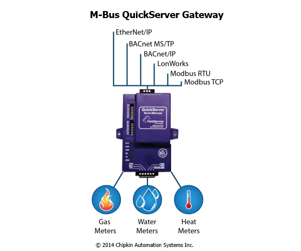
QuickServer is a high-performance, fully configurable, cost-effective Building Automation gateway for integrators to easily interface devices to networks in commercial buildings, industrial plants and campuses.It is one of the powerful interoperability gateways offered by FieldServer Technologies, which runs the robust FieldServer protocol conversion software on a highly cost effective platform backed by the experience and engineering expertise. With over 100 protocols available in the extensive FieldServer Driver Library, no other product can connect M-Bus to more products.
The M-Bus QuickServer Gateway can be configured to act as both a Master and a Slave M-Bus device depending on your needs. The maximum number of supported devices is limited to 64 as an M-Bus Master whereas the number rises to 250 when it's used as an M-Bus Slave.The FieldServer configured as an M-Bus Master device has the ability to change each slave to a desired standard M-Bus baud rate automatically. However, in an M-Bus Slave device configuration, it has the ability to change its own baud to a desired standard M-Bus baud rate if requested by the Master.The M-Bus master interrogates the slave devices as the gateway acts as a Client. It will request information from the slave devices and receive and process only the expected responses. Also, since QuickServer powers the M-Bus network internally, there is no need for the added expense and wiring of a level converter.
M-Bus – Topologies
Based on the distances involved, the data processing systems have been segregated into following categories:
- Global Area Networks (GAN): Encompasses world-wide
- Wide Area Networks (WAN): Covers continents or large-land masses
- Local Area Networks (LAN): Limited to specific geographical areas communication up to a few kilometers, for example, laboratories, office buildings and company premises.
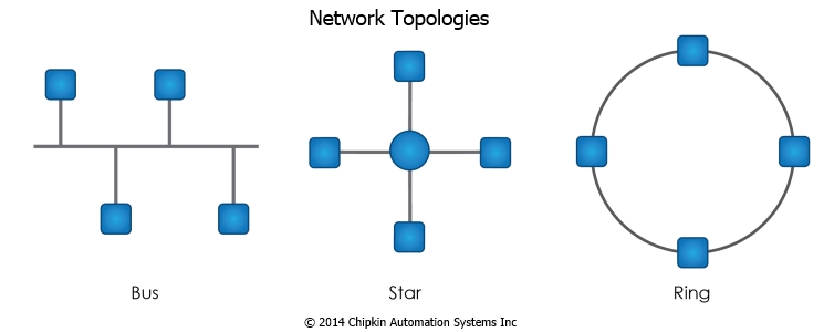
Now, local area networks are primarily used to connect terminals, computers, measuring equipment and process automation modules with one another. Topologies i.e. the different methods applied for linking various components in a local network system are classified below:
Star Topology
In this method, each component is coupled to a central processor unit via a separate transmission line and the data transfer to the central unit can take place either sequentially or simultaneously. However, one negative point associated with this topology is the increased requirement for cabling.
Ring Topology
In this topology, the components get connected in a ring structure and the data transfer happens from point to point. This arrangement suffers from the drawback that if by chance, single equipment fails; the whole network will turn inactive.
Bus Topology
In this case, a common transmission line is used to connect all the components, which leads to only one equipment data-transfer at one instant. This is a very economical and effective topology as it enables both broadcasting (transmission of data to all components) as well as multi-casting (transmission to specific groups in the system). This arrangement never stops working because of single component failure.
Of all the above-mentioned topologies, the bus topology is the most reliable and cost-effective one. The major requirements put by consumer utility meters on such a bus system are explained as follows:
- Largely, it requires the interconnection of various devices over long distances( i.e. covering up to several kilometers). Since the data sent by the meters is used for end-user billing, a high degree of transmission integrity is mandatory for the bus.
- Since only a relatively small amount of information usually gets transferred, it is possible to dispense with high speed of transmission. To ensure this high degree of transmission integrity, the bus must be exceptionally insensitive to external interference caused by either capacitive or inductive coupling.
- Also, in order to prevent ground loops, the slave should be electrically isolated.
- Another requirement for the bus is a low cost for the complete system. Hence, the transmission medium used should not require shielding and the slaves might get remotely powered via the bus. Using as few components as possible can also minimize the cost of individual meters.
- The cost of installing and servicing the system must be considered carefully as it can be curtailed by incorporating protection against reversed polarity. Provisions must be made for the connection of additional facilities such as Life Insert during the bus operation….
M-Bus – Access Techniques
In a serial bus system, the transmission happens serially i.e. bit after bit, sequentially in time and via a common medium whereas in parallel bus systems, the individual bits, which form a character, are transmitted simultaneously by a certain number of data lines. Although parallel transmission happens quickly, it increases cost owing to extra cable and connector requirements.The serial bus systems are more popular and economical. They incorporate various forms as shown in the figure below:
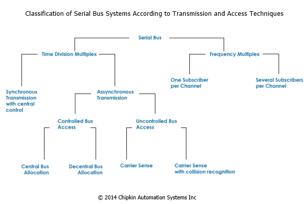
They can be broadly classified and allocated a channel depending upon the multiplex technique used, be it frequency multiplex or time division multiplexing. To prevent bus conflicts or collisions and ensure that each
participant transmits for at least a given minimum time, the sharing of the bus among stations must be implemented with an allocation logic system.With central allocation logic, the central bus controller receives the request and takes the decision about the user and when it can occupy the bus. Various methods are used to register this bus occupation request:
- Direct registration by means of an individual branch line to each equipment
- Periodical interrogation (polling) of the participants as to their transmission needs
- Requests sent on a common line with identification of the sender
- Allocation of the bus according to a predetermined time frame without taking account of individual requirements
The level of complexity required at individual stations in case of central allocation logic is quite minimal, which proves to be an additional advantage.Now, with decentralized allocation logic, each participant is provided with
functions, which allow him to recognize whether the bus is already in use or not. The most likely methods used to determine the bus occupation status are listed as follows:
- Mutual interrogation of stations by means of a request line for each station
- Periodical bus allocation, by passing "ownership" of the bus from station to station
- CSMA (Carrier Sense Multiple Access), where the participants have the ability to check whether the bus is transmitting data, and to transmit their own data if it is found to be free. Also, the stations are able to determine whether there is a bus conflict and in such a case, the transmission will be interrupted and repeated after an appropriate period of time.
Unlike central allocation logic, a great degree of logic complexity at each station is needed to implement decentralized allocation logic. However, this system also offers an advantage, as a fault in the central bus controller will never cause the complete breakdown of the bus.
M-Bus – Error Processing
There are varied reasons that may cause transmission error in a bus system. A few of them are mentioned below:
- Outside electromagnetic interference such as inductive coupling at mains frequencies
- High-frequency interference as a result of sparking at the brushes of motors or arcs of discharge lamps
- Capacitive coupling to other lines
- Directly coupled currents from ground loops as a result of multiple grounds
Therefore, a bus system must timely ensure that the transmission errors are recognized and corrected. In order to facilitate this, additional information always gets supplied with the data to be transmitted as it enables the data checking at the reception itself.
In case of asynchronous transmission, an extra parity bit is often transmitted with each character. This parity bit is constructed so that the parity conditions (an even number of ones, or an odd number of ones) are fulfilled.
In another method, a block-check character is created from specific mathematical operations, for example, addition without carry (Check Sum), which is derived from all the data. Subsequently, the receiving station can detect whether there have been transmission errors or not by comparing the check character it has received with the calculated one. However, the addition of the parity bit allows only the recognition of an odd number of faulty bits.
In order to rectify errors, the recipient sends an acknowledgment indicating that the transmission has been either accurate or erroneous. Also, the transmitter keeps track that the receiver acknowledges the reception of data within a given time frame. If the time limit is exceeded or if a transmission error gets reported, then the sender repeats the transmission procedure all over again for a fixed number of times.
In order to determine the security of a character code, the "Hamming Distance" error-detection technique may also be applied.
M-Bus – Physical Layer
There was had been no bus system available for carrying out remote meter readings until Professor Dr. Horst Ziegler developed M-Bus. He hailed from of the University of Paderborn (in association with Texas Instruments Deutschland GmbH and Techem GmbH) . Based on the ISO-OSI Reference Model, his concept was to realize an open system, which could utilize almost any desired protocol.
The OSI model defines the communications functions in seven layers, each of which has a virtual connection to the appropriate layer of the communicating partner. Each layer except the physical layer acquires the necessary services from the layer below it. Now, in case of M-bus, instead of seven, there are only four layers provided with functions i.e. the physical, the data link, the network and the application layer. Since the M-Bus is not a network, it does not need a transport or session layer and hence the levels four to six of the OSI model are empty.
The basic physical connection for exchanging signals between the communicating partners takes place in the lowest layer. Everything from the mechanical to the electrical coupling, transmission medium, distances involved, pin connection and bit representation etc. is specified here.
The M-Bus is a hierarchical system where communication gets controlled via a master using "Central Allocation Logic". The M-Bus comprises the master and number of slaves (i.e. the end-equipment meters and a two-wire connecting cable) as shown in the figure below:
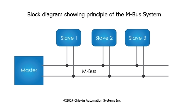
In order to create an extensive and cost-effective bus network, a two-wire cable was used together with serial data transfer. An M-Bus system can embrace many zones, each having its own group address, and interconnected via zone controllers and higher level networks. Each zone may further include segments, which in turn are connected by remote repeaters. However, normally an M-Bus system entails only a single segment, which is connected via a local repeater to a Personal Computer (PC) acting as master. Such local repeaters transform the M-Bus signals into signals suitable for the RS232 interface.
Some of the important points that must be taken into account before using an M-Bus network are mentioned below:
- A two-wire standard telephone cable is used as the transmission medium for the M-Bus.
- The maximum distance between a slave and the repeater is 350 m and this length corresponds to a cable resistance of up to 29 W.
- This distance applies for a maximum of 250 slaves and a standard configuration having Baud rates between 300 and 9600 Baud.
- The maximum distance can be increased by limiting the Baud rate and cutting down on slaves. However, the bus voltage in the Space state must never fall below 12 V in a segment owing to the remote powering of the slaves.
- The bus-interface i.e. the interface between the slave and the bus system must take the current it needs from the bus system.
- If possible, the complete slave should be fed from the bus and in case, the bus fails, it must instantly switch over to battery operation, else, the provision must be made to safeguard significant data.
- If the slaves are getting power only from batteries, a battery life of sufficient years must be attained in order to reduce maintenance costs.
- The two bus lines can be easily interchanged without affecting the slave operations because the bus interfaces of the slaves are polarity independent. In addition to protection aspects, this also helps in simplified installation of the bus system.
M-Bus – Troubleshooting
If the M-Bus communication stops working, one needs to figure out whether it concerns the whole network or just single (or several) meter(s) in particular. The following steps must be performed for troubleshooting the complete network:
- Examine the bus wiring, the AMBUS ? PC link, and use a compatible PC loaded with the read-out program that runs under DOS.
- Measure the voltage and current at the central station with the aid of a multi-meter. Make sure that the M -Bus voltage lies between 24 and 36 VDC and the supply voltage between 12 and 24 VAC.
- Split the main network into smaller networks by removing branches from it, and try to communicate with these sub-networks.
- If the central station is an AMBUS -FA, check to see if the PC can at least communicate with its processor.
- Disconnect the AMBUS from the mains and all meters from the network, inspect the wiring & cable, change to secondary addressing, correct the baud rate or even replace the serial card.
- Locate the problem with the aid of a protocol/logic analyzer, examine the voltage on the bus by means of an oscilloscope and if needed, substitute the central station.
Guidelines for rectifying one (or more) particular non-responding meter(s) are listed below:
- If the meter is accessible, make sure that it is powered and then read its bus and series numbers, baud rate and access counter from the display.
- Try to establish a point-to-point link with the meter disconnected from the bus.
- Exchange the meter with the operational one in order to determine if the problem lies with the network or with the meter itself.
- If the meter is inaccessible, try to communicate with it from the central station using various baud rates.
- Check the wiring & the bus cable, modify the primary address or the baud rate, spot the defective M-Bus interface, move either the CALEC or the light source, or cover the interface with a strip of opaque adhesive tape.
M-Bus Transceiver TSS721
To cut down on the number of components needed and subsequently the cost of slaves, Texas Instruments Deutschland GmbH introduced an IC called the Transceiver TSS721.
In addition to the transmission and reception of data as per the M-Bus specification, this IC also enables translation to and from the operating voltage of the connected microprocessor for better communication.
Significant features of this Transmitter-Receiver, TSS721 that communicates at baud rates, from 300 to 9600 Bauds, can be accounted as follows:
Reversed Polarity Potrection
TSS721 offers an integrated protection against reversed polarity via the
external protection resistors Rv as shown in the figure below: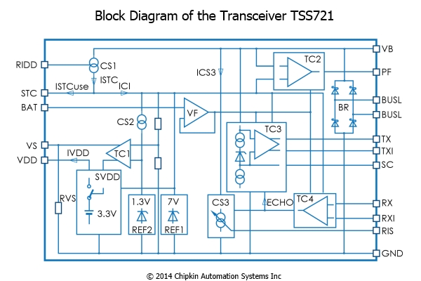
Powering of the Processor
TSS721 feeds a constant voltage of 3.3 V at VDD Pin, in order to supply power to a microprocessor. When limited to a standard load, according to the data sheet this processor may consume an average current of about 600 ?A. For pulse current requirements, use is made of the reservoir capacitor STC.
Signaling of the Bus Voltage Failure
TSS721 provides prompt indication of the failure of the bus voltage at the PF-Pin (power fail), so that the processor has time to store its data in an EEPROM, whilst powered by the reservoir capacitor. In addition, the transceiver permits the connection of a battery to the VDD Pin should the bus fail, by means of FET at the VS Pin (voltage switch).
The basic transmission and reception procedure of TSS721 is clearly shown in the circuit diagram.
M-Bus – Advantages & Limitations
The use of M-Bus networks for automated remote reading offers a huge set of advantages both for the supply enterprises and for their customers. Some of the great benefits of M-Bus systems are enlisted below:
- Enables fully electronic reading of all data without any error and at a very fast speed.
- Avoids all kind of human interventions and shuns entry of supplier personnel into the private premises.
- Facilitates instant automated reports and creation of databases for all consumers.
- Ensures reliability and high data security, preventing malicious attempts of data-manipulation.
- Allows meter-mounting in distant and difficult places that are hard to access.
- Makes short reading intervals possible i.e. readout can be done even every minute, which reduces the problems associated with tenant change or tariff amendments.
- Provides statistics and information on consumption optimizing i.e. energy management in buildings.
- Minimizes cost for both suppliers and customers to a great extent.
As compared to the wireless systems, M-Bus networks tend to be considerably cheaper and dependable. In case a problem arises in M-Bus network, only the cable segment gets replaced whereas in a wireless system, a whole new concentrator is required. So, the price for troubleshooting in two networks is almost incomparable.
Another great feature of M-Bus systems is that all the network information is neither stored in the slave or master device. This means that whenever a node gets replaced in the network, the system works the same, and data stays safe in the server. M-Bus speeds are, however, relatively slow at 2400bps while in wireless, the speed stays at approximately 38.4kbps.
There is one disadvantage of M-Bus systems. If the cable is not damaged but rather short-circuited then the whole network will become unreachable and unreadable irrespective of the source of the problem. Therefore, while building M-Bus network, segmentation and other foolproof techniques must be carried out properly to avoid such malfunctions.
Funny Video About Resetting Password
Some people must have been frustrated by the recent heartbleed bug. Click the image to watch the funny video.

![]()
Visit our Facebook page for more videos.
Safety Picture

Submit any related pictures to us.