Multistack and FieldServer Products - FS-8705-18 Connector and Assembly Instructions
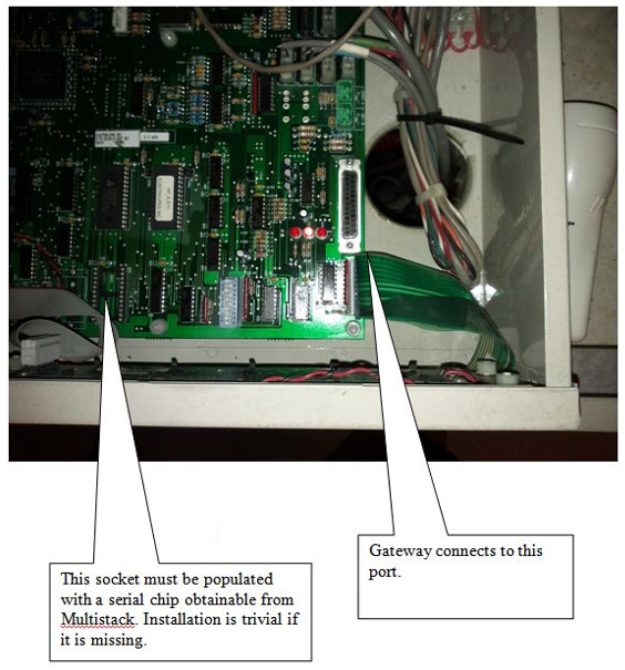
Before anything else, ensure your multistack controller has the RS232 socket populated. See the image below which shows which socket must be populated and where the FieldServer QuickServer Gateway connects. This article will help you integrate your Multistack devices using Multistack converters such as the QuickServer Gateway.
Possible shipped accessories with the purchase of a Multistack FieldServer
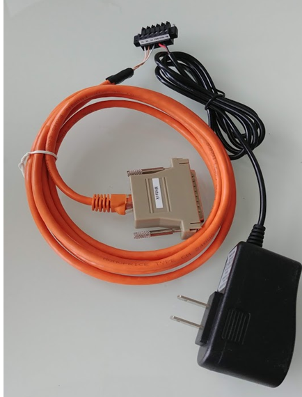
Below is a list and images of the possible shipped accessories with the purchase of a Multistack QuickServer Gateway.
- One or Two Ethernet patch cables, one lugged into the RJ45 port of the pre-built 25-pin connector (Item 2)
- One male 25-pin connector created as per the instructions below
- One spare unprepared male 25-pin connector (loose wires)
- One unprepared 9-pin connector (loose wires)
- One Mini tester with the reducers to DB9 and a couple of gender benders depending on availability
Sometimes we might ship multiple sets of items 1,2,3 (one set for each chiller we will connect to)
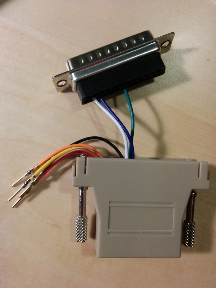
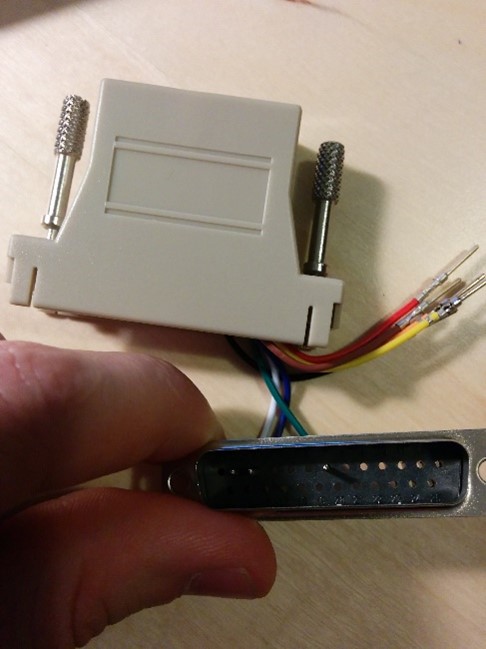
How to prepare Item 2 of the list above. See image to the right. Please note that on the bottom (where the cables are inserted) you can see the number written above/bottom of each hole.
Place each cord to the hole #:
- White on hole number 2
- Blue on hole number 3
- Green on hole number 7
- Cut the other wires short so that they fit inside the connector
Patch Cable Connection
Cut the other end off a patch cable and cut all wires except Orange-White, Brown, Blue-White
Connect these wires as shown below. See the image below for how it should look. The other side of the patch cable connects to the 25-pin connector as per above.
- RS232-Tx connects to patch cable Orange-White (very left hole)
- RS232-Rx connects to patch cable Brown (second left hole)
- RS232-Gnd connects to patch cable Blue-White (Third left hole)