Oct. 2009 Chipkin Automation Newsletter
![]()
CAS Newsletter October 2009
| IN THIS ISSUE |
|
| Cartoon |
|
|

Trouble Shooting BACnet IP / Ethernet
|
Requiersa tools:
Tips:
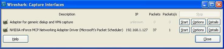
How to Capture with Wireshark 1. Capture Main Menu
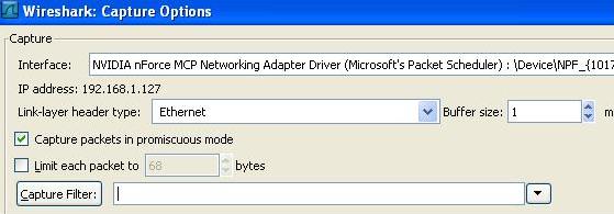
2. Interfaces On Capture Menu a. You get a list of network adapters. Pick the one connected to the network of interest. Its probably not the wireless adapter. Most often its the adapter with the packet count increasing
b. Select the Start button or c. Select the options button to define a capture filter. Define the filter and click start. 3. A list of packets accumulates on the screen.
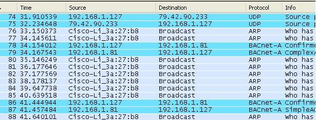
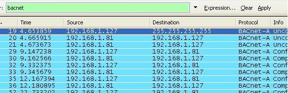
4. Apply a Display Filter. More on display filters later. For now simply type bacnet into the filter field and click apply.
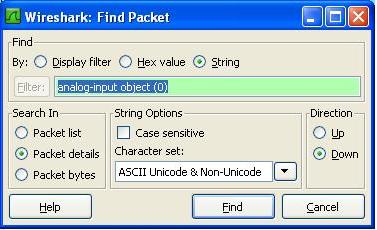
5. Find the packet you are interested in. Click on it to select it. A breakout of the selected packets data is shown below the packet list.
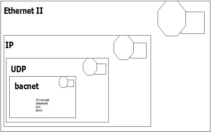
6. You can break out the level of detail by expanding the sections of the packet. Think of a bacnet packet as a letter you send to a bacnet device. When you take it to the bacnet post office. The clerk says he does not understand the address. He passes it to the UDP clerk. The UDP clerk takes your letter and puts it in
a bigger envelope. He addresses the envelope with a UDP address. He passes it to the IP post office clerk. The IP clerk takes your letter and puts it in a bigger envelope. He addresses the envelope with an IP address. He passes it to the
Ethernet post office clerk. The Ethernet clerk takes your letter and puts it in a bigger envelope. He addresses the envelope with a hardware address and sends it to that computer. When it arrives the process is reversed until finally the
contents are passed to the bacnet application.
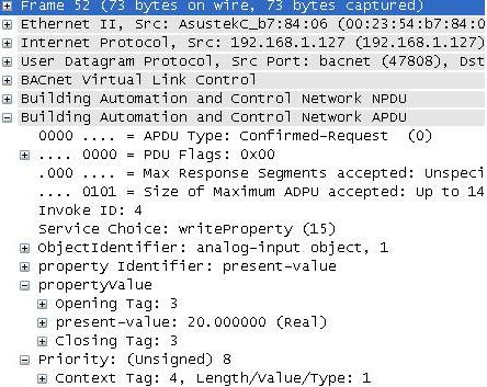
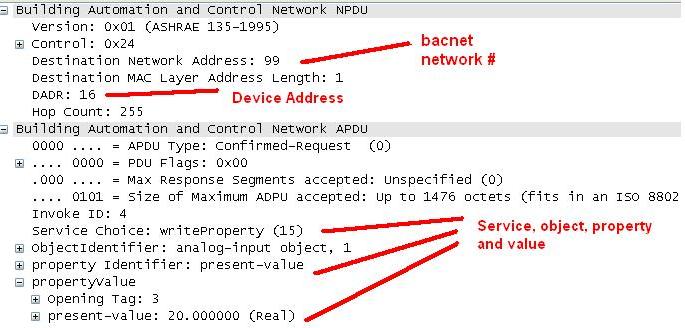
Ethernet packets contain packets from other higher level protocols nested inside each other. You drill down to see the detail you want. In the example below you can see the bacnet packet nested inside a UDP (User Datagram Protocol) which is nested inside an IP protocol packet which is in turn nested inside an Ethernet packet. Drilling down into the Bacnet packet you can see the concept is carried even further. The bacnet service is a write to analog input #1. That is wrapped up with some information about the device the device number and network number is contained inside the NPDU.
7. Drill down to see the BACnet info
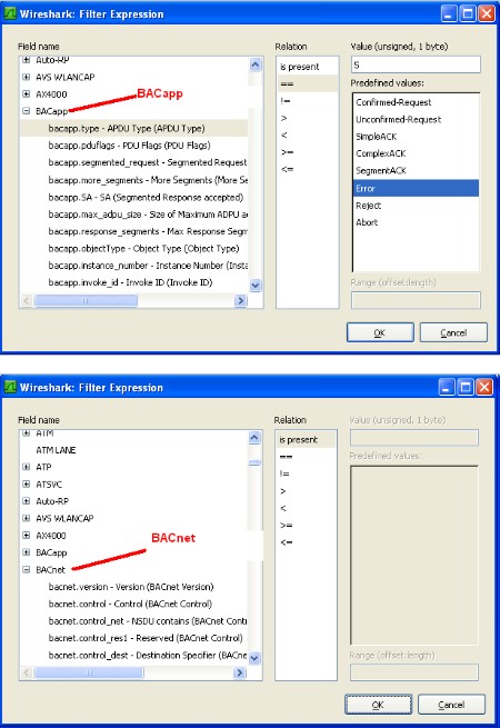
How to Select (Filter) What you Capture with Wireshark Before you start a capture you can specify a capture filter. The effect of the filter is to prevent all packets being captured. Doing this can save space when you save the log and it might make it easier to find the packets you are interested in. However, there is some risk that you might filter out the packets of interest. For example, a BACnet device might not operate correctly because it is being hammered with packets from another protocol being sent incorrectly to the BACnet device. Our advise is to capture as much as possible and then filter what is displayed.
Here are some sample filtersExamples Capture only traffic to or from IP address 172.18.5.4: host 172.18.5.4 Capture only traffic to or from IP address 172.18.5.4 but exclude all FieldServer RUINET messages host 192.168.1.81 and port not 1024 Capture traffic to or from a range of IP addresses: net 192.168.0.0/24 or net 192.168.0.0 mask 255.255.255.0 Capture traffic from a range of IP addresses: src net 192.168.0.0/24 or src net 192.168.0.0 mask 255.255.255.0 Capture traffic to a range of IP addresses: dst net 192.168.0.0/24 or dst net 192.168.0.0 mask 255.255.255.0 Capture only bacnet traffic: Assumes every device is compliant and is using the standard port. port 47808 |


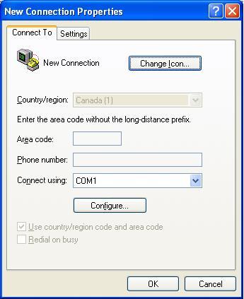
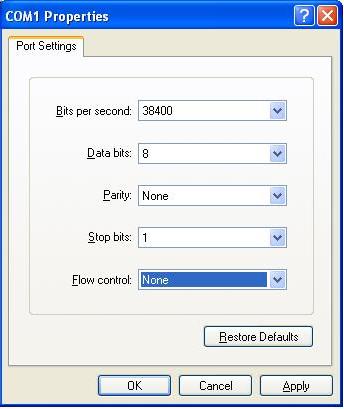
Trouble Shooting BACnet MSTPOne badly behaved device on a MSTP trunk can cause a collapse in performance. To understand why consider this one example of what can go wrong. RS485 is s shared trunk. When two devices transmit at the same time this causes a collision. In simple terms think of the messages interfering with each other and corrupting each other so neither message is recognizable. To prevent this happening and to allow for multiple master on a network, BACnet has chosen a token based system. Only devices with the token can initiate a message transaction. To keep things running smoothly, BACnet has some demanding timing requirements. For example, a device passes the token on. The receiving device has 15msec to use the token. Lets say it responds in 18msec. During that interval, the original device doesn't see the token being used so it send the token again. As it sends it, the 2nd device uses the token (3 msec late). Now the messages from the 1st and 2nd device clash. The 2nd device thinks it has the token and starts to use it. The 1st device thinks the token got lost and starts to poll for a new master. Messages clash, causing contention and eventually both devices recover to a valid state using the protocol rules. These rules require waiting various timeout periods. All the waiting, collisions and recovery waste time and bandwidth. If this happens often (as it will because one device doesn't meet the spec) then you can lose significant bandwidth. Strategy Capture Traffic using USB-485 converter Use a tool like BACspy Or Use Hyperterminal Analyze Traffic Use a tool like BACspy online or Offline Or Perform a manual analysis Configure HyperTerminal Select the COM port which corresponds to your USB converter Set the Baud Rate correctly Set the other parameters as shown
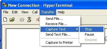
Use this menu to start and stop the capture
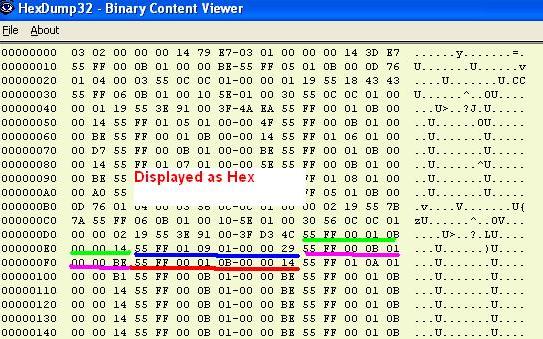
As the messages are captured you will see these non-human readable characters fill the screen.
Inspect the captured data before you leave site to see if it usable. You need a viewer capable of displaying the hex bytes. Here is a free download and hex viewer. Open the log file. To ensure you captured useful data look for messages that begin 55 FF. All BACnet MSTP messages begin with the same codes. If you dont see any then this may mean you captured at the wrong baud rate or some other setting is wrong. It is also possible that there is no BACnet communication.
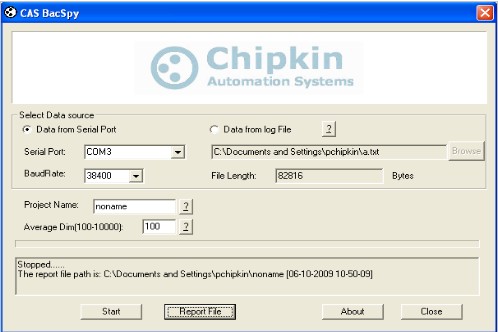
http://hexdump32.salty-brine-software.qarchive.org/_download2.html You can use the CAS BACspy tool BACspy automates this process of capture and analysis.

|


Power Over EthernetPOE is a technology that provides electrical power to a Powered Device using conductors in a CAT5 cable. Power is delivered by means of a DC voltage and maximum current rating. Typical Power Sourcing Equipment devices are network switches. Even though there is a standard (IEEE 802.3af) there are a number of factors you should watch for as this technology emerges and evolves because as usual the devil is in the details. Check for IEEE 802.3af standard compliance on data sheets. A number of products dont comply with the standard. If you are merely a consumer, any IEEE 802.3af compatible device will work with any other. If your PoE devices are not IEEE 802.3af compliant, best stick with one brand, or at least with PoE devices known to be compatible with your favorite brand. Jargon Powered Devices (PD) The device being powered. Power Sourcing Equipment (PSE) The device supplying the power Endspan PSE Also known as POE Switches. The switch (or other network endpoint) supplies the power. Midspan PSE The Power is injected onto the cable outside of the network end point. You use Midspan PSEs when you are using a standard switch with no POE capability but you want the Ethernet cable to carry the power to the field device. You thus inject power at a midpoint Modes This jargon term is used to define whether power is carries on the data lines or the spare line. The PSE determines the mode. The standard requires that PDs support both modes. The PSE may not activate both modes at the same time. Mode A The data lines also carry the power. Mode B Spare or non-data lines carry the power. POE Power Class A term that describes the amount of power supplied. The PSE sets the class based on how the PD signals it for power. During the start up phase, the PD draws a specific amount of current. This tells the PSE what class to operate at.
POE Powering Stages A PSE must never send power to a device that does not expect it. For this reason power is not simply applied when a connection is made. Rather the PSE progresses through these powering stages. Signature PSE probes the device to see if it is 802.3af compliant by looking for a signature impedance of 25kOhm using a voltage of between 2.7 and 10V. If the signature is not seen then the process terminates and no power is supplied. The Signature stage restarts when cable is reconnected. Classification PSE supplies a voltage and the PD draws a specific current. Based on the current draw the PSE determines the power class to be supplied. Startup The PD starts up as the supplied voltage reaches a level sufficient for the device to operate normally. Normal Operation or Disconnect If you remove the cable the PSE stops supplying power. Reconnection means that the powering stages begin again with the signature stage. If the PD stops using the supplied power (draws less than 10mA for 400mSec) the PSE stops applying power returns to the signature stage. Watch Out for Heat Dissipation Two Issues hotter cables and hotter switches Some of the power supplied will be lost as heat in the CAT5 cable. Heat degrades the insulation (at best) or causes fires at worst. Based on the 802.3af spec the TIA permits a max of 100 CAT5 POE cables to be bundled together. Thus is based on the spec of 350mA. There are devices that can supply more current and hence the heat issue becomes more pronounced. The POE switches will draws more power and hence dissipate more heat from internal losses. Polarity The POE standard does not specify which lines will carry the positive voltage and which will carry the negative voltage. If the PD meets the POE spec there are no issues. If it doesn't then you could end up with a polarity reversal and damage. Multi Mode Cat5 Some device use non-data lines in the CAT5 cable for other purposes such as voice. If such a device was connected to a PSE that doesn't meet the POE standard then it could be supplied a voltage it doesn't expect and this could cause damage. Connecting non POE devices Not an issue of the PSE meets the standard because it wont apply power unless the field device presents the correct signature. If it doesn't meet the spec, power could be applied continuously which means the the non POE field device could see a voltage that it wasn't designed for and this could cause damage. Voltage Level Different vendors have implemented POE at different voltage levels. These PSEs are non standard. Eg. Cisco 48V Intel 12V or 24V Symbol 12V or 24V Apple 48V |
|
| SAFETY PICTURES |
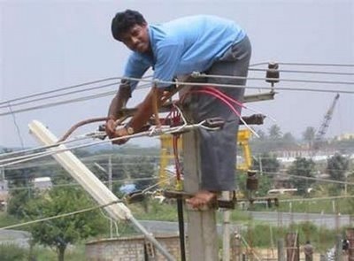
 Submit any related pictures to us. Submit any related pictures to us. |
| 2009 Chipkin Automation Systems [email protected]BACnet is a registered trademark of ASHRAE. |