RS485 - What Are Possible RS485 Polarity Issues
RS485 is an electrical communication standard used by Modbus RTU, BACnet MS/TP, and many other building automation protocols. This article covers issues related to the polarity of the RS485 differential balanced line. A differential balanced line consists of two wires (negative and positive). Binary '1' is indicated by the voltage in the positive wire is greater than the negative wire. Binary '0' is indicated by the positive wire having a voltage less than the negative wire. The difference in voltages is expected to be at least 0.2v according to the RS485 standard, although not all devices comply with this. If the difference between positive and negative wires is less than 0.2v, then the bus is idle.
V+ V > 0.2v : 1
V V+ > 0.2v : 0
0.2v
Four-wire RS485 has two differential balanced lines. Two-wire RS485 uses a single differential balanced line.
RS485 polarity labels differ between manufacturers. According to the RS485 standard, the two terminals are,
A
for negative and B for positive.
Most manufacturers will instead use + and –, or some variation such as D+, D . Some manufacturers will
label
inputs as A and B but get the polarity backward, so A is positive. It is important to read the manual rather
than assuming a manufacturer follows the standard.
RS485 has a reputation for being polarity insensitive because under normal conditions most devices will automatically determine which wire in the differential balanced line is positive and which is negative. This is because during the idle state the positive wire should have a slightly higher voltage than the negative wire. A typical RS485 message, with the polarity of the positive and negative wires during the idle state, is a red X, [X]. A multi-meter can be used to verify that the positive wire is higher than the negative wire during idle.
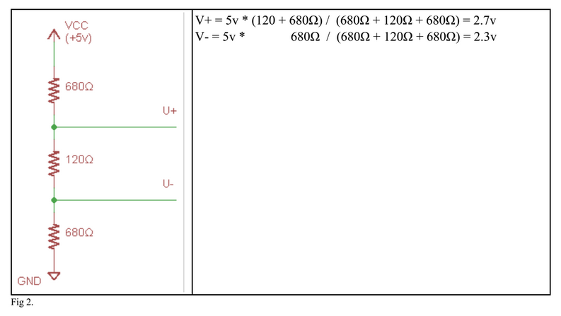
The positive wire has a higher voltage than the negative wire during idle state because RS485 differential
lines
use termination resistors. The line is idle when no devices are sending data, which means all devices have
switched their output to high impedance. In this state, the voltage levels of wires are primarily set by the
termination resistors. Figure 2 shows an example set of RS485 termination resistors and the voltage they
produce
on the wires during an idle state.
Possible Problems With Automatically Detecting Polarity:
- Termination resistors are not set up properly.
- Electrical noise interferes with voltage levels during an idle state.
- The ground connection to the termination resistors does not match the ground of the devices.
- The Vcc voltage connected to the termination resistors does not match the Vcc of the devices.
- The RS485 device does not support polarity detection. (this is very rare).
Ways to Avoid Polarity Issues:
- Connect positive and negative wires to the device as specified in the manual.
- Ensure proper termination resistors.
- Run a common (ground wire) to all devices and the termination resistors.
- Verify which wire is positive using a multimeter during the idle state. Do not assume wire coloring is correct.
Did you know that we also carry Integration Solutions?
Chipkin has integration solutions for almost every situation. We specialize in network protocol communications and have over 20+ years of experience. Click for more information: