Strain Gauge as a Precision Measurement Tool
Strain gauges are widely used as precision measurement instruments for detecting mechanical deformation caused by applied forces. By converting small physical strains into measurable electrical signals, strain gauges enable accurate monitoring of displacement, force, load, pressure, torque, and weight across a wide range of engineering and industrial applications.
Strain gauges are used across many industries and applications, with different materials and constructions optimized for specific operating conditions. For an overview of common strain gauge materials and constructions, see our related article on strain gauge materials and constructions .
Fundamentals of Stress and Strain Measurement
Any external force applied to a stationary object produces internal resisting forces known as stress. The resulting displacement or deformation is referred to as strain. Strain may be tensile or compressive and is typically extremely small, requiring highly sensitive measurement techniques.
A strain gauge converts this mechanical deformation into a measurable electrical signal, allowing engineers to quantify displacement, force, load, pressure, torque, or weight with high accuracy.
Key Measurement Characteristics
- Commonly used for load, weight, and force detection
- Measures minute changes in distance between points on a solid body
- Operates on the principle that electrical resistance changes under strain
- Typical resistance values range from 30 Ω to 3 kΩ (unstressed)
- Compact form factor, often smaller than a postage stamp
An ideal strain gauge is small, lightweight, low-cost, easy to install, and highly sensitive to strain while remaining minimally affected by temperature and environmental conditions. In practice, real-world installations must account for several secondary influences.
Gauge Factor and Sensitivity
Strain gauges convert mechanical motion into an electrical response. The proportional relationship between mechanical strain and the resulting change in electrical resistance is defined by the gauge factor (GF).
When a conductive element is stretched, its length increases and cross-sectional area decreases, producing a measurable resistance change proportional to the applied strain.
 Where, RG is the resistance of the undeformed gauge,
 R is the change in resistance caused by strain, and
 is strain. Accurate strain measurement depends on both material stability
and precise signal conditioning.
Measuring Circuits and Signal Conditioning
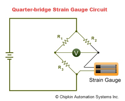
Because strain-induced resistance changes are extremely small, strain gauges must be connected to sensitive measuring circuits. The most common approach is the Wheatstone bridge, which enables precise detection of resistance variation.
Modern strain-gauge transducers often use quarter-bridge, half-bridge, or full-bridge configurations to improve sensitivity and temperature compensation. Output is typically expressed in millivolts per volt of excitation.
Temperature and Environmental Effects
Temperature variations can significantly influence strain gauge measurements. Changes in ambient temperature affect both the sensing element and the base material to which it is bonded.
Differences in thermal expansion coefficients may introduce apparent strain, while temperature-induced resistance changes can shift calibration references. Compensation techniques and stable materials are therefore critical in precision applications.
Installation and Diagnostic Checks
Proper installation is essential for reliable strain measurement. After mounting but before full wiring, base resistance should be verified to confirm sensor integrity.
- Measure isolation resistance between the gauge grid and specimen
- Check for induced voltages with bridge power disconnected
- Verify stable excitation voltage before measurement
- Confirm bond integrity by applying controlled pressure
These diagnostic steps help ensure that measurement errors are not introduced during installation or commissioning.
Typical Measurement Applications
- Experimental stress analysis in mechanical engineering
- Structural load monitoring and validation
- Aircraft and aerospace component testing
- Industrial force and weight measurement systems
