Types of Strain Gauges?
Introduction
Various means like mechanical, optical, acoustical, pneumatic, or electrical can be used to measure the deformation (strain) of an object. Earlier mechanical devices such as extension meter (extensiometer) were used to measure strain by measuring the change in length and comparing it to the original length of the object. However, mechanical strain gauges offer certain limitations like low resolutions. Besides they are bulky and difficult to use.
Further, capacitance and inductance-based strain gauges were introduced but these devices' sensitivity to vibration, their mounting requirements, and circuit complexity restricted their usage.
Next are the photoelectric gauges. These gauges use a light beam, two fine gratings, and a photocell detector to generate an electrical current proportional to strain. A photoelectric gauge can be as short as 1/16 inch but its usage proves to be extremely costly and delicate.
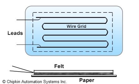
In 1938, the first bonded, metallic wire-type strain gauge was introduced. The metallic foil-type a strain gauge is constructed of a grid of wire filament of approximately 0.001 in thickness, bonded directly to the strained surface by a thin layer of epoxy resin. When a load is applied to the surface, it gets strained and experiences a change in length. This resulting change in length is conveyed to the resistor and the corresponding strain is measured in terms of the electrical resistance of the foil wire, which varies linearly with strain. Other types of Strain Gauges are described below.
Semiconductor Strain Gauges
In the year 1970, the first semiconductor strain gauges were developed for use in the automotive industry. Semiconductor strain gauges exhibit the following key features:
- Unlike other strain gauges, semiconductor strain gauges are based upon the piezoresistive effects of silicon or germanium and measure the change in resistance with stress as opposed to strain.
- The semiconductor bonded strain gage is a wafer with the resistance element diffused into a substrate of silicon.
- No backing is provided for the wafer element and bonding it to the strained surface needs extra care since only a thin layer of epoxy is used to attach it.
- The size of a semiconductor strain gauge is much smaller and the cost much lower than for a metallic foil sensor.
- Advantages include higher unit resistance and sensitivity.
- Disadvantages: Greater sensitivity to temperature variations and tendency to drift as compared to metallic foil sensors. Also, the resistance-to-strain relationship is nonlinear, varying 10-20% from a straight-line equation. However, by means of computer-controlled instrumentation, these limitations can be overcome via software compensation.
Thin-film Strain Gauges
The thin-film strain gauge is a more advanced form of strain gauge as it doesn't necessitate adhesive bonding. A thin-film strain gauge is constructed by first depositing electrical insulation, usually a ceramic onto the stressed metal surface, and then depositing the strain gage onto this insulation layer. Techniques used to bond the materials molecularly are:
- Vacuum deposition
- Sputtering method
Advantages
- Since the thin-film gage is molecularly bonded to the specimen, the installation is very stable and the resistance values experience less drift.
- The stressed force detector can be a metallic diaphragm or beam with a deposited layer of ceramic insulation.
Diffused Semiconductor Strain Gauges
A further improvement in strain gage technology was introduced with the advent of diffused semiconductor strain gages since they purge the need for bonding agents. The main features are listed below:
- By eliminating bonding agents, errors due to creep and hysteresis also are eliminated.
- The diffused semiconductor strain gage employs photolithography masking techniques and solid-state diffusion of boron to molecularly bond the resistance elements.
- Diffused semiconductors are frequently used as sensing elements in pressure transducers.
- Limitations include sensitivity to ambient temperature variations, which can be compensated by intelligent transmitter designs.
Advantages
- Small size
- Inexpensive
- Accurate and repeatable
- Available with a pressure range
- Generate a strong output signal
Bonded Resistance Gauges
Following are the chief characteristics of bonded resistance strain gauges:
- They are reasonably inexpensive.
- They can pull off overall accuracy of better than +/-0.10%.
- They are available in a short gauge length and have small physical sizes.
- These strain gauges are only moderately affected by temperature changes.
- They are extremely sensitive and have low mass.
- Bonded resistance strain gages can be employed to measure both static and dynamic strain.
- These types of strain gauges are appropriate for a wide variety of environmental conditions. They can measure strain in jet engine turbines operating at very high temperatures and in cryogenic fluid applications at temperatures as low as -452*F (-269*C).
Selection of a proper Gauge
Three primary considerations in strain gauge selection are mentioned below:
- Operating temperature
- Nature of the strain to be detected
- Stability requirements
In addition, choosing the right carrier material, grid alloy, adhesive, and protective coating plays an important role in the success of the application.
Did you know that we also do BACnet Integration Solutions?
Chipkin has BACnet solutions for almost every situation. We have over 20+ years of experience in BACnet integration, check out our BACnet Products:

