Using Modbus Scanner to Write Digitrip 3000 (Protective Relays) Control Registers
Introduction
Digitrip 3000 Protective Relays are manufactured by Cutler-Hammer (Eaton Corporation). Typically, Modbus TCP registers are provided as control registers for these Digitrip 3000 Protective Relays in the Digitrip 3000 Control documentation.
It is very important to note that ALL of these Modbus TCP registers which are provided in the above mentioned Digitrip 3000 Control documentation, are Holding registers (Analogue Outputs).
Using Modbus Scanner and Writing the Registers
The following steps should be followed in order to successfully write to the Modbus registers using Modbus Scanner.
1. Opening the Modbus Scanner
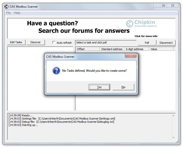
If there are no tasks defined in the scanner, then the first thing asked by the Modbus Scanner on opening is "No tasks defined, would you like to create some?". This is shown in the screenshot shown in figure - 1 below.
If there are tasks already defined in the system, then just a click is required on "Edit Tasks" option on the upper left-side of the screen shown in the figure - 1, and clicking on "Edit Tasks" will populate the tasks in the left-side space on the screen.
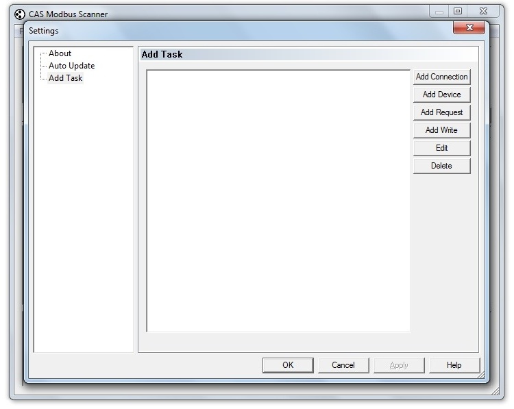
Clicking "Yes" to the question in the screen shown above, will lead to the settings screen shown in figure - 2 (shown below).
2. Adding a Connection:
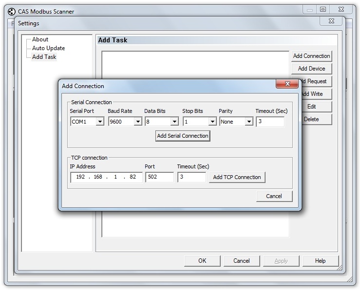
Next step is to add a connection. Clicking on "Add Connection" tag opens up the following screen (figure - 3).
Here, the IP Address is the IP Address of the gateway (Field Server) and Port is to be kept 502 (default). Clicking on "Add TCP Connection" here, adds the connection to the task window.
3. Adding Device:
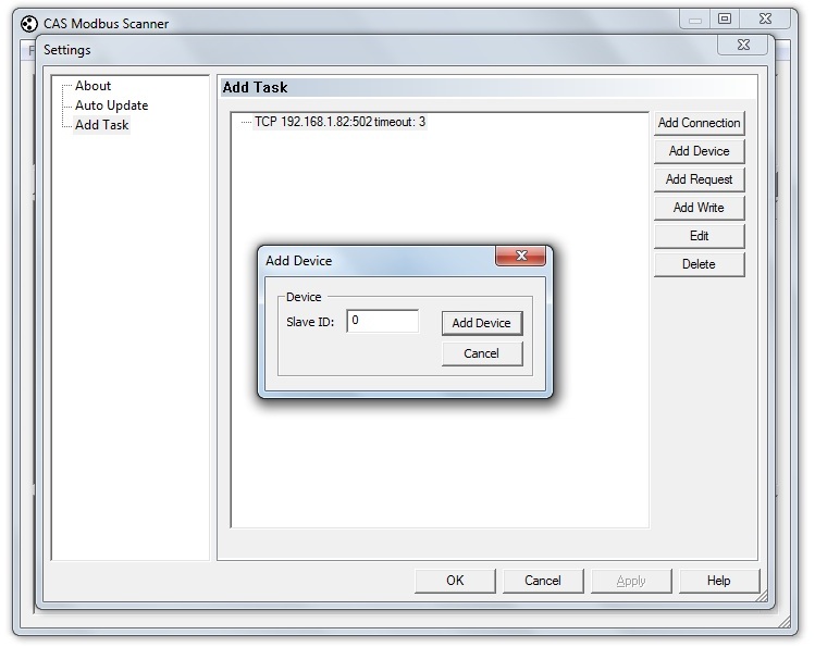
To add the device, click the "Add Device" tag on the Settings window. It opens up a dialogue box as shown in figure - 4 below.
Here, the Slave ID is the ID of the gateway (fieldserver). A click on the "Add Device" adds the device to the hierarchy in the task window.
4. Adding a Request:
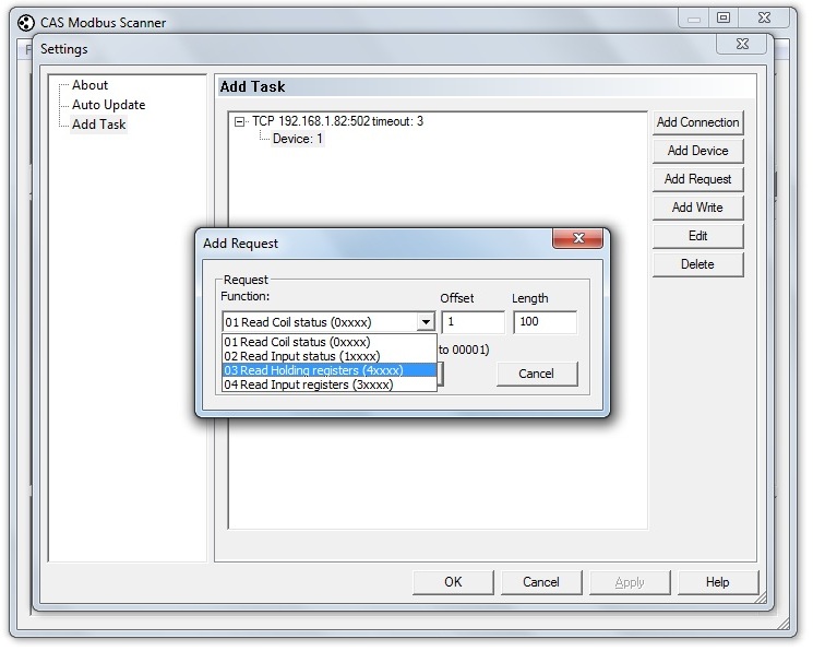
To add Request to the task, click on the "Add Request" tag on the right-side of the "Settings" window. It opens up a dialogue box as shown in figure - 5 below.
Here, it is important to note that ALL of the Modbus TCP registers provided in the Digitrip 3000 Control documentation, are Holding registers (Analogue Outputs). Therefore, as shown in the screen shot above, choose function 03 "Read Holding Registers (4xxxx)" from the function drop-down box. Offset and length are to be kept according to the details mentioned in the control documentation.
5. Writing to the Modbus Registers:
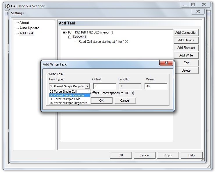
To write to the Modbus registers click "Add Write" tag in the "settings" window. It opens up a dialogue box as shown in figure - 6 below.
Make an appropriate choice from the "Task Type" drop-down box as shown above. "Force Single Coil" writes to the single Coil, "Force Multiple Coils" writes to multiple coils, "Preset Single Register" writes to the single holding register and "Force Multiple Registers" writes to multiple registers.
