CAN Bus Protocol - 10 Minute Lesson
Intro to CAN Bus:
CAN (Controller Area Network) is a two-wire differential serial communication protocol used for real-time control. The CAN Bus Protocol was originally developed for the Automotive Industry - in order to connect the transmission, airbags, antilock braking/ABS, cruise control, electric power steering, audio systems, power windows, doors, mirror adjustment, battery, and recharging systems for hybrid/electric cars, etc.
CAN is a multi-master (Peer-to-peer network) message broadcast system that specifies a maximum signaling rate from 125kbps to 1 Mbps. It provides for 2048 different message identifiers.
![]()
CAN was developed by Robert Bosch GmbH in 1983.CAN bus is one of five protocols used in the on-board diagnostics (OBD)-II vehicle diagnostics standard. Each year, about 1 billion CAN nodes are sold.
Competitive Advantage and Application
Benefits:
- Low Cost: ECUs (ECU = Electronic Control Units) communicate via a single CAN interface, i.e. not direct analog signal lines, reducing errors, weight, costs.
- Centralized: The CAN bus system allows for central error diagnosis and configuration across all ECU.
- Robust: The system is robust towards the failure of subsystems and electromagnetic interference.
- Efficient: CAN messages are prioritized via IDs so that the highest priority IDs are non-interrupted.
- Flexible: Each ECU contains a chip for receiving all transmitted messages, decide relevance and act accordingly - this allows easy modification and inclusion of additional nodes
Fig. 1: Example of CAN
and Without CAN in automotive application
CAN Bus is used extensively in:
- Transportation systems (rail vehicle, aircraft, marine, etc.)
- Industrial machine control systems
- Home and building automation (e.g. HVAC, elevators)
- Mobile machines (construction and agriculture equipment)
- Medical devices and laboratory automation, as well as in many other embedded and deeply embedded applications.
System Components and Network Structure
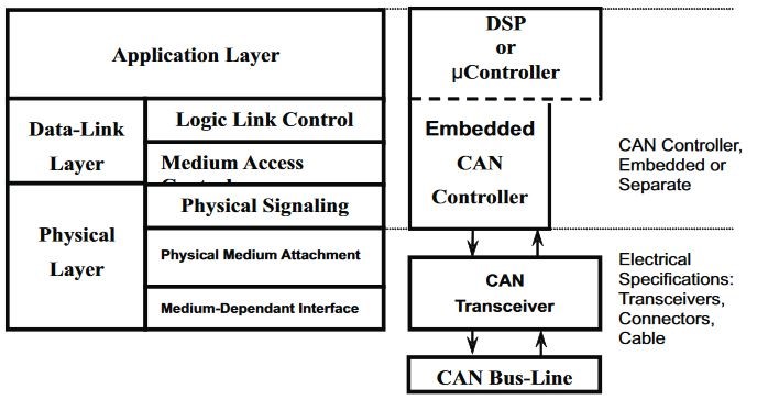
Fig. 2: CAN BUS OSI Architecture
CAN Bus Types
CAN High Speed (CAN 2.0B)
- Speed: Up to 1Mbps
- Range: 40m
- 29bit Message Identifier
- Termination with 120 ÃŽ© Resistor
CAN Low Speed (CAN 2.0A)
- Speed: Up to 125Kbps
- Range: 500m
- 11bit Message Identifier
- overall termination resistance should be about 100 ÃŽ©
CAN FD (Flexible Data Rate)
- Speed: Up to 15Mbps
- Range 10m
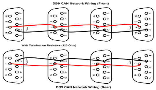
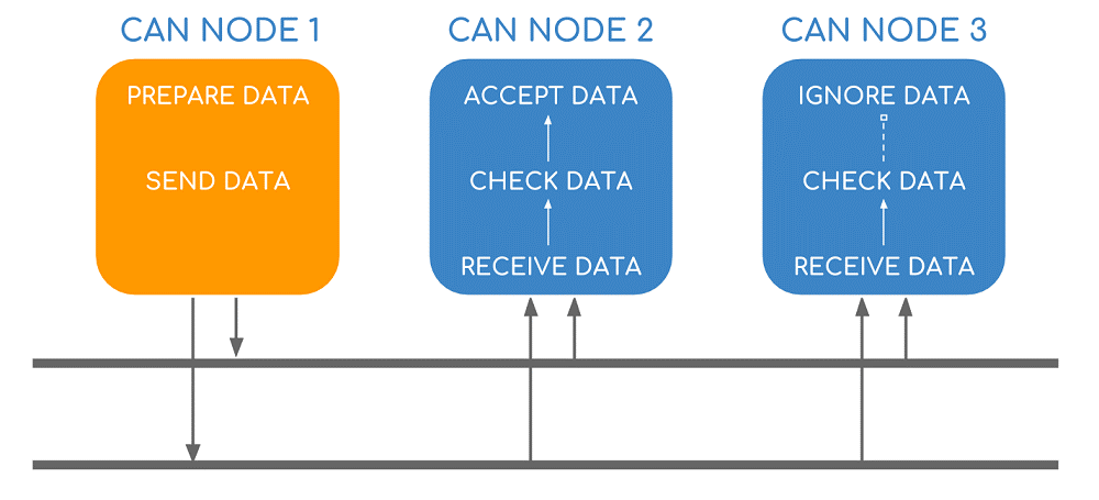
Fig. 3: DB9 CAN BUS Notwork Wiring Diagram
Is CAN Synchronous or Asynchronous?
CAN data transmission uses a lossless bitwise arbitration method of contention resolution. This arbitration method requires all nodes on the CAN network to be synchronized to sample every bit on the CAN network at the same time. Therefore, some call CAN synchronous. (Unfortunately, the term synchronous is imprecise since
the data is transmitted without a clock signal in an asynchronous format) All nodes are connected to each other through a two-wire bus. The wires are a twisted pair with a 120 ÃŽ© (nominal) characteristic impedance.
NOTE: The CAN bus must be terminated. The termination resistors are needed to suppress
reflections as well as return the bus to its recessive or idle state.
Topology
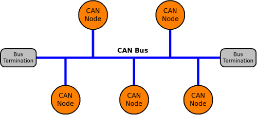
Fig. 4: CAN BUS Topology
CAN allows multiple devices (referred to as "nodes"), two or more nodes are required on the CAN network to communicate. The complexity of the node can range from a simple I/O device or embedded computer or a gateway. Each node requires a: Central processing unit: microprocessor, or host processor CAN controller: often an integral part of the microcontroller CAN Transceiver: Defined by ISO 11898-2/3 Medium Access Unit [MAU] standards.
How many nodes can you have?
In CANopen, there are unique addresses available for up to 127 nodes on the bus. However, the practical physical limit of nodes is about 110 units per bus. In J1939, there are 253 unique addresses available for the bus.
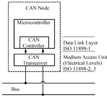
Fig. 5: CAN NODE
How does the Data Transmission Mechanism work?
The CAN specifications use the terms "dominant" bits and "recessive" bits. Dominant is a logical 0 (actively driven to a voltage by the transmitter) Recessive is a logical 1 (passively returned to a voltage by a resistor) Idle state is represented by the recessive level (Logical 1) If one node transmits a dominant bit and another node transmits a recessive bit, then there is a collision and the dominant bit "wins". A 'message' is a packet of data that carries the information to be exchanged between the nodes. Each message in CAN has a unique identification number.
The following video explains, in detail, how a CAN Bus works:
With a message-based protocol, other nodes can be added without re-programming since the units connected to
the bus has no identifying information - like node addressing. So, there is no change needed in the software and hardware of any of the units connected on the bus. Arbitration is the process of the
negotiation between the devices and decides which of them can take over the bus for itself (Recommended
Read: https://www.linkedin.com/pulse/bus-arbitration-can-controller-area-network-abdul-rehman-anwer/
and https://www.mikroe.com/blog/can-bus).
To ensure there are enough transitions to maintain synchronization, a bit of opposite polarity is inserted after five consecutive bits of the same polarity. This practice is called bit-stuffing and is necessary due to the non-return to zero (NRZ) coding used with CAN. The stuffed data frames are destuffed by
the receiver.
Ready to go deeper? Continue with a more detailed look at CAN bus frames, arbitration, and error handling .
Integration Solutions
Chipkin has integration solutions for almost every situation. We specialize in network protocol communications and have over 20+ years of experience. Click for more information: