Get to know your Power Meter – What is Real, Apparent and Reactive Power
First – A Simple Question
Right or Wrong? Power = Voltage x Current that statement is correct for DC systems but there are two major complications for AC systems.
- The value of current and voltage keeps changing. Which value do you use ?
- The voltage and the current may not be in phase. Multiplying the current and the voltage when they are not in phase requires and adjustment to compensate for the phase. It is this phase shift that forces us to define Real, Apparent and Reactive Power.
- This phase shift occurs when a power source feeds an inductive or capacitve load". Most loads are either inductive (motors) or resistive (heaters) and therefore the phase shift is typically in one direction.
- A motor has a winding. A wound conductor essentially defines an inductor. Thus the winding presents the resistance of the wound wire and the inductance resulting from the winding.
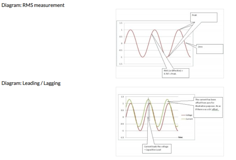
RMS or Effective Value
Peak values in the alternating voltage or current curves only lasts a short instant. They are not really representative of the ability of the voltage and current to do work and thus they are not used in Power Calculations.Scientists use a statistical method to define the effective values. It is called the RMS or Root-Mean-Square values. The result of the definition is that: Veff / rms = 0.707 x V peak The same applies to current too.TIP: You can reasonably assume that all the Voltages and Currents reported by a Power Meter are reported as RMS or Effective values unless otherwise indicated. TIP: Most multi meters report RMS values
Apparent Power
Apparent Power is the power delivered by a power source to a load like a motor. In almost all real world situations that use AC, you need to supply more power (Apparent Power) to a device than it will do work (Real Power).The (vector) difference between the two represents the work done to overcome the inductive and capacities effects of the load.Apparent Power is measured in units of VA – Volt-amperes. These are actually Watts but we use the new unit name to reduce confusion. Thus when you see VA on a data sheet you can reasonably conclude that they are talking about Apparent Power.Apparent Power is calculated:S(Common symbol for Apparent Power) = Veff / rms x Ieff / rms – Single Phase Calc
Power Factor and Phase
Power Factor is calculated: PF = Cosine ( phase angle in radians)Power factor has no engineering units.The value of PF ranges from -1 to 0 to 1 (lagging – none – leading)Loads that only present a resistive load (no capacitance or inductance) have a PF of 1.Inductive Loads
Current phase lags the Voltage Typical – Transformers and motors (wound conductors) Capacitive Loads
Current phase leads the Voltage Typical – Buried Cables, capacitor banks There is nothing 'wrong' with having a power factor that isn't 1.0.
Real Power and Reactive Power
Think of Real Power as useful power – a measure of how much work is being done.The units of Real Power are Watts.Real Power is calculated : P(Real) = S(Apparent Power) x pf Reactive Power is the (vector) difference between Apparent Power and Real Power. The energy used to produce the Reactive Power is stored in the magnetic/electrical field of the Inductive Load. In the case of the capacitive load the magnetic/electrical field of the Inductive Load produces the Reactive Power. Reactive Power cannot be harnessed to do useful work.Reactive Power is identified by the symbol : Q The engineering units of Reactive Power are VAR – Volt-amperes Reactive. These are also Watts but we use VAR so that we know we are talking about Reactive Power.
THD – Total harmonic Distortion (also called Distortion)
In simple terms THD is a measure of distortion reported as %. If a device (any active device but think of rectifiers, variable speed drives … as practical examples) is given a sine wave as in input the output is never a faithful 100% reproduction of the input. A series of harmonics of the original wave distort the original wave form. The THD % is an attempt to 'numberize' the degree of distortion to allow for comparison. The % number is somewhat controversial because some harmonics are more important than others and there is no weighting. THD(%) = 100 * SQRT[(V22 + V32 + V42 + … + Vn2)] / Vt Where V2, V3 are the RMS values of each voltage harmonic and Vt is the total RMS output voltage.
Sag / Swell or Dip / Surge
Duration is 0.5 cycle and greater. Voltage sags are the most common power disturbance. Voltage sags can arrive from the utility. In most cases, sags are generated inside a building. For example, in residential wiring, the most common cause of voltage sags is the starting current drawn by refrigerator and air conditioning motors.Sags do not generally disturb incandescent or fluorescent lighting. motors, or heaters. However, some electronic equipment lacks sufficient internal energy storage and, therefore, cannot ride through sags in the supply voltage. Equipment may be able to ride through very brief, deep sags, or it may be able to ride through longer but shallower sags.
Under / Over Voltage
Over Voltage is an increase in effective voltage to more than 110% for longer than one minute. Under Voltage is a decrease in effective voltage to less than 90% for longer than one minute. Take care with this definition because it tends to change from vendor to vendor.
Transient Voltages / Spikes / Surges
Refers to short duration (less than 1 cycle) events. Low frequency transients are often called "capacitor switching transients". High frequency transients are often called impulses, spikes, or surges. They can be caused when a discharged power-factor-correction capacitor is switched on across the line.High frequency transients are caused by lightning, and by inductive loads turning off. Typical rise times are on the order of a microsecond; typical decay times are on the order of a tens to hundreds of microseconds. Often, the decay will be an exponential damped ringing waveform, with a frequency of approximately 100 kHz.Extremely fast transients, or EFT's, have rise and fall times in the nanosecond region. They are caused by arcing faults, such as bad brushes in motors, and are rapidly damped out by even a few meters of distribution wiring. Standard line filters, included on almost all electronic equipment, remove EFT's.
Did you know that we also do Modbus Integration Solutions?
Chipkin has Modbus solutions for almost every situation. We are experts in Modbus RTU/TCP communication and carry a wide variety of Modbus products: