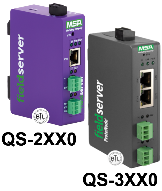
FieldServer Setup, Hot Standby Mode 1 and 2
Attention - The hot standby features of FieldServers are present in all firmware and will continue to be so for the foreseeable future. However, the feature is no longer officially supported. If you need this feature please call in and ask to speak to Peter Chipkin
Project Overview: Using a FieldServer in a Hot Standby Mode
Hot Standby mode, also known as redundant or standby mode, is a configuration in which two identical systems are deployed, with one actively processing data while the other remains on standby. In the event of a failure in the active system, control is transferred to the standby system to ensure continuous operation and prevent interruptions in critical processes. This redundancy setup enhances system reliability and availability, making it particularly valuable in environments where downtime is not acceptable.
FieldServers can be configured and set up to work in Hot Standby mode in two forms.
Hot Standby Mode 1, also known as true Hot Standby, is a redundancy configuration utilizing two FieldServers: an Active and a Passive unit. This mode offers simplicity in implementation but comes with inherent limitations.
Alternatively, Hot Standby Mode 2 (Dual Redundant Mode) provides a more sophisticated redundancy solution suitable for complex applications, albeit requiring a more intricate configuration process.
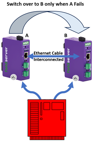
Hot Standby Mode 1 (true Hot Standby)
Two FieldServers are used in this configuration, one designated as Active and the other as Passive. The Active FieldServer transmits and receives information from the remote Nodes and transmits a constant heartbeat signal to the Passive unit.
On failure of the Active FieldServer, the heartbeat stops and control switches to the Passive FieldServer which consequently becomes the Active FieldServer. This FieldServer now polls the host for data and updates its Data Arrays and from this point maintains communication with the host.
The heartbeat can be transferred via 2 Ethernet ports using either 2 hubs (Figure X) or 2 crossover cables. Two are used in order to preserve the redundant capability of the entire system.
Hot Standby Mode 1 is ideal for straightforward applications where the objective is simply to prevent a FieldServer hardware failure from interrupting communications.
Limitations of Hot Standby Mode 1:
- There is a time latency involved in the switchover process. It takes about 2 seconds to achieve a switchover from passive to active mode, and the time taken for data polling and Data Array update needs to be added to this.
- The Passive FieldServer will not respond to polling.
- Data Arrays on the passive FieldServer are not updated until switchover, polling and a successful response from the host has been achieved.
For further information on how to set up a FieldServer using Hot Stanby Mode 1, see the following links:
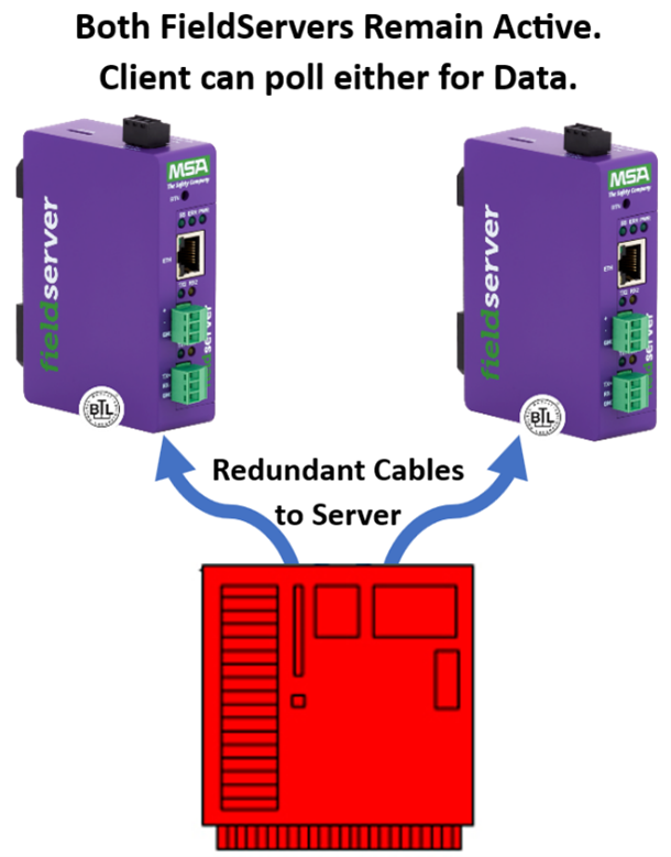
Hot Standby Mode 2 (Dual Redundant Mode)
In this mode, both the Primary and the Secondary system are continuously active and the Data Arrays of both systems are continually updated. Each system keeps an image of what is happening in its complementary system. Figure XII shows how the dual image allows for multiple data paths, which in turn provide a high level of data redundancy.
Hot Standby Mode 2 is intended for more complex applications where requirements are more stringent. Consequently, configuration is more complex.
The heartbeat can be transferred via 2 Ethernet ports using either 2 hubs (Figure X) or 2 crossover cables. Two are used in order to preserve the redundant capability of the entire system.
Mode 2 Hot Standby introduces the following new concepts to FieldServer configuration.
- Single Port Server
- Dual Port Server
- Tiers - SCADA and PEX
- Keepalive Map Descriptors
- Server Name
ENOTE 002: FieldServer Hot Standby Operation
Hot Standby Terminology
|
Term |
Description |
|
Active FieldServer |
The FieldServer actively polling the field Nodes |
|
Standby FieldServer |
A FieldServer which is running, but is not polling field Nodes, nor responding to Client polls. It will assume active status if the Active FieldServer fails to issue a heartbeat in the designated time frame |
|
Failover Timeout |
The time interval between the Active FieldServer failing and the Standby FieldServer preparing to become the Active FieldServer. |
|
Transfer Interval |
The total time interval between the Active FieldServer failing and the Standby FieldServer actually resuming communications as the Active FieldServer |
|
Primary FieldServer |
The FieldServer designated to be the Active FieldServer on system startup |
|
Secondary FieldServer |
The FieldServer designated to be the Standby FieldServer on system startup |
|
Commbit Data Array |
Bit Data Array that shows all the online Nodes, one bit per Node address. The practical limit is 255 Nodes, the offset corresponds to the Node_ID |
|
NodeStat Data Array |
Int Data Array that shows all the status of all Nodes, one integer per Node address. The practical limit is 255 Nodes, the offset corresponds to the Node_ID. The value of the integer corresponds to the current Node status |
|
Hot Standby Status Data Array |
A Data Array showing the status of all Hot Standby FieldServers in a pair, e.g. which FieldServer is active, is it the primary or secondary, is the standby FieldServer active, why did the switchover occur, 0 |
Possible FieldServer Configurations for Redundant, Hot Standby operation
Configuration 1: Single FieldServer, single connection to field node. This is not a hot standby or redundant configuration. It is included here for comprehensiveness.
Configuration 2: Single FieldServer, dual connection to field node. This mode of operation requires the field node to have two serial ports.
For any given node configured in the FieldServer, there is a "Backup Connection". If there is a single communication failure, the kernel will attempt the next poll out the backup connection. If this poll is successful, then the backup connection is used from this point onwards. If the poll fails, then the kernel will alternate between the primary and the backup connection until the number of allowed retries is used up. Once this happens, the node is marked offline.
Configuration 3: Hot Standby FieldServer Pair, Ribbon Cable, single connection to field node. This is the classic hot standby mode, where the ribbon cable shares the FieldServer serial ports with a single field node serial port. If the primary FieldServer fails, the secondary FieldServer takes over. If a single port on the primary fails, at present, the primary FieldServer will continue to be the active FieldServer.
Configuration 4: Hot Standby FieldServer Pair, Ribbon Cable, backup connection to field
node.
Combination of Configuration 3 and Configuration 2.
Configuration 5: Hot Standby FieldServer Pair, No Ribbon Cable, single connection to field node from each FieldServer. Although this is labeled as single connection to field nodes, each FieldServer in the pair is connected to one of two ports on field node. When the Active FieldServer fails, the standby FieldServer will automatically take over. The question is, what happens if a single cable is cut? We want to switch to the standby FieldServer and attempt to recover communication. If however a node fails, communication recovery is not possible, and we want to prevent flip-flopping between the FieldServers. This can be prevented by looking at the "Health Data" of the Standby FieldServer. (See section "Monitoring Standby FieldServer Health from the Active FieldServer")
Configuration 6: Hot Standby, No Ribbon Cable, backup connection to field node. This is not a legal configuration. Included for comprehensiveness. (It would require the PLC to have four serial ports).
Heartbeat Connections
Ribbon Cables This is included for comprehensiveness, but is no longer used
Serial Connections The heartbeat message is sent over dual serial ports.
Ethernet The heartbeat message is sent over Ethernet links.
Theory of Operation
Operation of Active FieldServer The active FieldServer sends heartbeat messages at very regular and short intervals. The messages may contain data array data which is used to update the data arrays of the standby FieldServer, so that if and when the standby becomes active, any clients polling for data will be sent current data values.
Operation of Standby FieldServer The Standby FieldServer listens to the heartbeat messages. If the heartbeat messages fail to arrive within the Failover Timeout, it will switch to Active mode and start to send heartbeat messages to keep the other FieldServer firmly in standby mode (assuming it is still operational, or has been replaced).
- Mode 1: FieldServer fails.
This is relatively straightforward. The Standby FieldServer fails to receive the heartbeat messages, and after the configured Failover Timeout, takes over as the Active FieldServer. If the previously active FieldServer restarts, it will remain as the new Standby FieldServer until it no longer gets a heartbeat message. - Mode 2: Cable is cut, or serial port on FieldServer or field node fails.
This is more complex. It is quite possible that a cable is cut or disconnected, and we want to try and anticipate this condition.
Hot Standby FieldServer configuration issues
Configuring a FieldServer for Hot Standby
- Establishing Hot Standby Operation
- Defining a "Hot_Standby" connection in configuration file.
The FieldServer can determine that it is configured to act as part of a Hot Standby Pair when a "hot_standby" connection is defined in the configuration file. At startup a particular FieldServer would now need to determine if it should become the Active or the Standby FieldServer. At startup the FieldServer will wait for a heartbeat message from an Active FieldServer for a random time of between 2.0 and 2.8 seconds. If the Failover Timeout has expired, the FieldServer will become the active FieldServer and start sending heartbeat signals on the Hot Standby connection. Typically this will be used in Configuration Example 3 above (Section Configuration 3:). - Explicit configuration.
The FieldServer can be explicitly configured as either a Primary or Secondary FieldServer by way of a separate hot standby configuration file. This file will be stored on the FieldServer flash disk. If the FieldServer is configured as a Secondary FieldServer, then it will wait an additional one-second before starts up. This will give the Primary FieldServer (if one exists) time to become the Active FieldServer when the hot standby pair is switched on at the same time. If both FieldServers in the hot standby pair are configured the same way, then essentially the mode of operation reverts back to the automatic configuration explained above. Typically this will be used in the Configuration Example 5 above (Section Configuration 5:). - Heartbeat Message Operation.
Heartbeat operation can be configured to work over a Serial Connection or over an Ethernet connection (new) or a combination thereof (new). This is achieved by setting the Connection_Mode of the relevant Connection to Hot_Standby. Two connections must be designated for Hot Standby operation. - Heartbeat Messages over a Serial Connection.
Configuration of this is straightforward and requires two serial connection cables to run between the Hot Standby FieldServer pair. - Heartbeat messages over Ethernet.
Sending heartbeat messages over Ethernet require that FieldServers of a particular Hot Standby pair be explicitly configured with a "Pair Name". This will be done in the hot_stby.ini file. When a FieldServer wants to send a heartbeat message over Ethernet, it would first send an Ethernet "Who-Is Standby" broadcast message containing the FieldServer Hot Standby "Pair Name". Any FieldServer that receives this message and has a matching Hot Standby Pair Name will respond with an "I-Am Standby" message. Subsequent heartbeat messages will be sent directly to the MAC address of the response message. Note that this mechanism does NOT USE IP ADDRESSING. This eliminates the need for annoying IP address configuration. It also means that the messages cannot be routed however, but this is OK since anybody who wants to put a router between the two FieldServers in a Hot Standby pair need to re-evaluate their career choices anyway. - Transferring Data Arrays to the Standby FieldServer.
An integral part of Hot Standby operation is to transfer "live" FieldServer data from the Active FieldServer to the Standby FieldServer. For this to work the Active and Standby FieldServers must have identical data arrays configured. This transfer of data is achieved by using the heartbeat signal. If the Connection_Mode is set to Hot_Standby_Data, then the heartbeat message will continuously transfer all the Data Array data to the standby FieldServer, one section of data at a time. If the Connection_Mode is set to Hot_Standby_Data_On_Change then only the part of the Data Array that changes will be sent to the Standby FieldServer. Typical applications for this are when the Data Arrays are very large and the data changes very seldom, such as for a fire panel system. In particular this would make sense if the heartbeat message is send over Serial connections. - Monitoring Standby FieldServer Health from the Active FieldServer.
Both FieldServers in a hot standby configuration pair can be configured with a Data Array containing the FieldServer status. This data will be send back to the Active FieldServer by including it into the heartbeat message acknowledge packet. Typically this would contain the last known status of all the nodes on the Standby FieldServer. This information could then be used by the Active FieldServer to decide if it should cause a FieldServer swap-around in case of a port/node failure. - Connecting and downloading to the Standby FieldServer.
Ruinet can be used to connect to the Active as well as the Standby FieldServer. For this to happen it will be required to know the IP_Address of the relevant FieldServer. Ruiping (using the 'h') switch can be used to determine the FieldServer IP Address, Hot Standby Pair Name and Hot Standby status (i.e. active or standby) - Naming convention and operation of the hot_standby ini files.
- If the FieldServer is configured as a Primary FieldServer, the file hsb_p.ini must be created and downloaded to the bridge.
- If the FieldServer is configured as the Secondary FieldServer, the file hsb_s.ini must be created and downloaded to the FieldServer.
- The syntax of the hsb_x.ini files is exactly the same as that of the standard FieldServer configuration file.
- The Hot Standby Pair Name must be set as the "Bridge" Parameter "HS_Pair_Name".
- Normally, the Hot Standby connections will also be configured in the ini files.
Legal Node States
This section describes all the existing and new legal states a node can be in.
Startup (new)
When the FieldServer starts up the initial state of a node is 'startup'. This
remains
until there has
been one successful poll, at which time the node will go into normal state. If there have been 3
retries and the node does not respond, then the state will become "Offline".
Normal (existing)
A node that is being polled, and is responding is considered normal. Note
that if
the response is
something like illegal memory address, this is NOT considered a reason to take a node offline.
Some PLCs will respond to some addresses but not others, eg Modbus 81 02 "illegal memory
address". Checksums, timeouts, etc. are still valid reasons to take a node offline.
Failing (existing)
If there is no response to a poll, the state of the node will become
Failing.
In this mode, there will
be a number of retries (as per configuration). If there is a backup connection defined, the kernel
will attempt to connect on the backup connection. Each retry is attempted at the retry interval time.
If the number of retries are used up, then the kernel will either attempt to switch over to the
standby FieldServer (new) if there is a standby FieldServer to switch to, or will mark the node
offline.
Offline (existing)
The kernel will attempt to recover the offline node at the recovery interval
time. If there is a
backup connection, then the kernel will alternate the connection for each attempt. If a node
responds, then the state will go to 'probation'.
Probation (existing)
Probation is a state after a node has reached offline, and is starting to
recover. For all practical
purposes the node is still considered offline. This state is to prevent a flaky connection from
coming online, then offline, then online etc. This probation state will currently last 1 minute, but is
planned to default to 1 second, so a user has to explicitly set this delay.
Trying Alternative Connection
If an alternative connection is available, then this is a
possible
state. However, there is a possibility
that this is a duplicate of the "Failing" state.
IP Addressing
Mode 1: Static Dual IP Addresses
In this mode, each FieldServer is provided with an IP Address via
the normal configuration
process. The IP Addresses remain static and the client software package has to detect that the
Primary FieldServer has gone offline and that the Secondary FieldServer with another IP Address
has taken over.
Client software such as FieldServer Technologies OPC driver will handle this occurrence seamlessly. Packages such as Intellution's Fix, without FieldServer Technologies OPC driver, will handle the switchover automatically, but report a communications failure during this period. Packages such as GE Cimplicity do not handle this process at this time.
Mode 2: Dynamic Single IP Address
This mode is for the client packages that do not handle Mode 1.
The Secondary FieldServer will
assume the IP Address and MAC address of the Primary on switchover. Most client software will still
report a
communications failure during this interval.
Mode 3: Bumpless Transfer IP Address
>This mode is the same as Mode 2, but the Standby FieldServer
closely shadows the state of the
Active FieldServer's socket by watching traffic on the network. If a switchover is required, the
client software will not be able to detect that another FieldServer has taken over the
communications.
Hot Standby Status Array
This table is obtained from ONLY the Primary FieldServer.
|
HSBY data array offset
|
Value
|
Description
|
|
0 |
1 |
Primary OK * |
|
1 |
1 |
Secondary OK * |
|
2 |
1 |
Primary is active * |
|
3 |
1 |
Secondary is active * |
|
4 |
1 |
Hot standby system OK |
|
5 |
x |
Number of times primary has become active * |
|
6 |
x |
Number of times secondary has become active * |
|
7 |
1 |
Cable N1-N1 is OK * |
|
8 |
1 |
Cable N2-N2 is OK * |
|
9 |
1 |
Hub N1 is OK, 0 Hub is NOK, 2 indeterminate |
|
10 |
1 |
Hub N2 is OK 0 Hub is NOK, 2 indeterminate |
|
11 |
1 |
Cable PFS:N1 is missing |
|
12 |
1 |
Cable PFS:N2 is missing |
|
13 |
1 |
Cable SFS:N1 is missing |
|
14 |
1 |
Cable SFS:N2 is missing |
|
15 |
1 |
Cable PFS:N1 is plugged into incorrect hub |
|
16 |
1 |
Cable PFS:N2 is plugged into incorrect hub |
|
17 |
1 |
Cable SFS:N1 is plugged into incorrect hub |
|
18 |
1 |
Cable SFS:N2 is plugged into incorrect hub |
|
19 |
1 |
Cable N1 is plugged into N2 of other bridge |
|
20 |
1 |
Cable N2 is plugged into N1 of other bridge |
|
21 |
1 |
Cable N1 is plugged into incorrect bridge partner |
|
22 |
1 |
Cable N2 is plugged into incorrect bridge partner |
|
23 |
1 |
Hot standby hubs not on independent networks e.g. joined by some link – not allowed for hot standby operation.3 |
|
24 |
1 |
Somewhere a backup connection used |
Node Status Array *
This is the data array which reflects the node state according to the Configuration Manual describing the possible states of each node in the FieldServer. Offset 1 represents the node state of Node ID 1.