Free Guide
Download our Modbus for Field Technician for free, or purchase this guide for $20 on amazon.com.

SqrdresizedWTBG__82782.1712180456.png?c=2 "Sqrd resized WT BG png - Sqrd resized WT BG png")

This protocol translator/gateway provides a wealth of features to enable data transfer between different devices and networks utilizing serial, Ethernet or LonWorks ports. The extensive library of FieldServer drivers provides easy interoperability with devices and networks used in building automation, HVAC, fire and process control industries.
The FS-B3510 is one of the FS-X30 Series FieldServers designed to meet the needs of system integrators in designing a complete interoperable system. The FS-B30 Series brings together the powerful FieldServer driver library with state-of-the-art gateway design. This FieldServer includes four serial connections (two RS-232, two RS-485), two Ethernet ports, and a LonWorks port. The multiport design allows for serial-to-serial interfaces or interface from mulitple serial products to an Ethernet or LonWorks network. The two Ethernet ports enable the integrator to connect a PC to download configuration changes without disturbing the system connections and without the additional cost of an external hub.
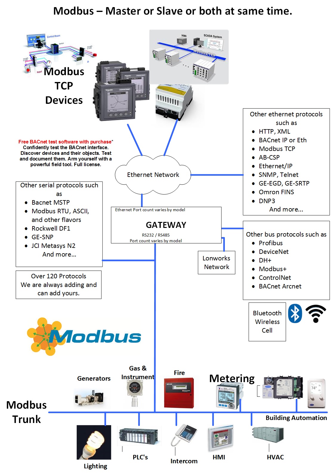
The Modbus RTU driver allows our FieldServer gateways to transfer data to and from devices over either RS-232 or RS-485 using Modbus RTU protocol. The Gateways are capable of being used as port expanders and can emulate either a Server or Client. The FieldServer is capable of supporting devices that use two Modbus Registers to transfer IEEE floating point format.
The information that follows describes how to expand upon the factory defaults provided in theconfiguration files included with the FieldServer.
There are various register mapping models being followed by various vendors.
The key difference between ADU and PDU is for example if Address_Type is ADU and address is 1, thedriver will poll for register 0. If Address_Type is PDU, the driver will poll for address 1.
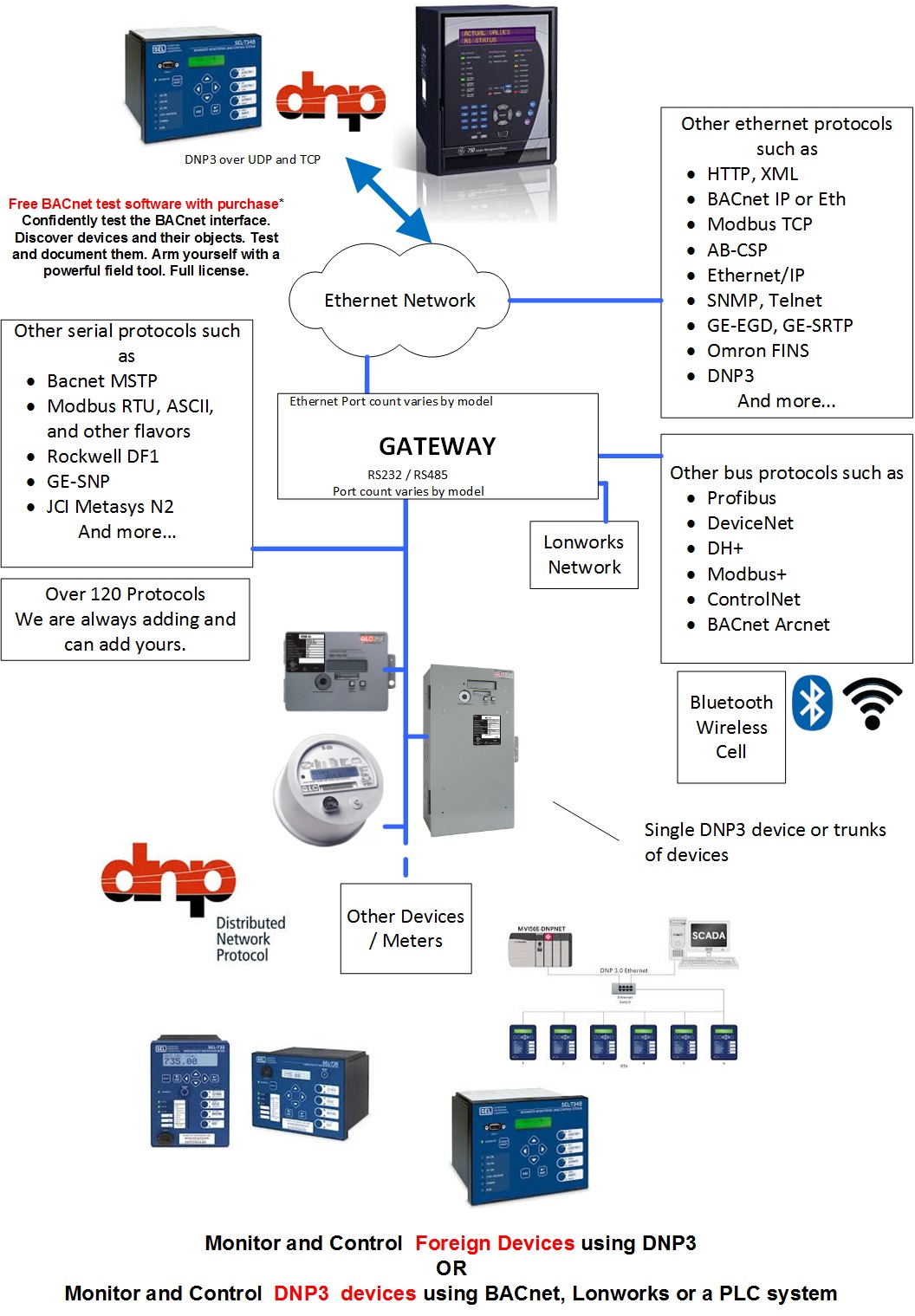
The Ethernet DNP 3.0 driver allows the FieldServer to transfer data to and from devices over Ethernet using DNP 3.0 protocol. The FieldServer can emulate either a Server of Client. The DNP 3.0 Ethernet Driver adheres to and supports the framework specified by the IEEE 1815-2012 Standard for electrical power system communications.
The following information was copied form the DNP 3.0 User Group Internet site.
The development of DNP3 was a comprehensive effort to achieve open, standardsbased Interoperability between substation computers, RTUs, IEDs (Intelligent Electronic Devices) and master stations (except inter-master station communications) for the electric utility industry. Also important was the time frame; the need for a solution to meet today's requirements. As ambitious an undertaking as this was, we reached this objective. And since the inception of DNP, the protocol has also become widely utilized in adjacent industries such as water / waste water, transportation and the oil and gas industry.
DNP3 is based on the standards of the International Electrotechnical Commission (IEC) Technical Committee 57, Working Group 03 who have been working on an OSI 3 layer "Enhanced Performance Architecture" (EPA) protocol standard for telecontrol applications. DNP3 has been designed to be as close to compliant as possible to the standards as they existed at time of development with the addition of functionality not identified in Europe but needed for current and future North American applications (e.g. limited transport layer functions to support 2K block transfers for IEDs, RF and fiber support). DNP3 has been selected as a Recommended Practice by the IEEE C.2 Task Force; RTU to IED Communications Protocol.
DNP3 is an open and public protocol. In order to ensure interoperability, longevity and upgradeability of, protocol the DNP3 Users Group has taken ownership of the protocol and assumes responsibility for its evolution. The DNP3 Users Group Technical Committee evaluates suggested modifications or additions to the protocol and then amends the protocol description as directed by the Users Group members.
DNP3 Features: DNP3 offers flexibility and functionality that go far beyond conventional communications protocols. Among its robust and flexible features DNP3 includes:
DNP3 was originally designed based on three layers of the OSI seven-layer model: application layer, data link layer and physical layer. The application layer is objectbased with objects provided for most generic data formats. The data link layer provides for several methods of retrieving data such as polling for classes and object variations. The physical layer defines most commonly a simple RS-232 or RS-485 interface.
DNP3 is very efficient for a layered protocol while ensuring high data integrity
DNP3 Benefits: Because DNP3 is based on the IEC 870-5 requirements, DNP3 is suitable for application in the entire SCADA environment. This includes RTU to IED communications, master to remote communications, and even peer-to-peer instances and network applications.
Being an object-based application layer protocol, DNP3 has the flexibility to support multiple operating modes such as poll-response, polled report-by-exception, unsolicited responses and peer-to-peer. It permits multiple masters and encourages distributed intelligence.
Users can expect many benefits from using DNP3. In the short term:
24V AC (+/-10%) or 12-30V DC @ 12W
Configuration/Diagnostic utilities
Power, Run, System Error, Configuration Error, and Node Offline
Ethernet connection– Link OK, Tx/Rx communication activity
RS-232/RS-485 – Tx/Rx communication activity
LonWorks - Activity
Memory upgrade for additional data points
Custom Configuration Service
Drivers available for a wide range of Ethernet and social protocols

If you are reading the documentation for sensor blocks, valves, and other devices, you must keep in mind that some vendors may document their hardware in different ways.
According to the Modbus standard, addresses are simply integers from 0 to 65,535 with the different address ranges being referred to as coils, holding registers, etc. However, some vendors will document their hardware using numerical prefixes which are not actually part of the Modbus address. This originated from some models of PLCs which used the Modbus communications protocol, and which also used numerical prefixes in their internal data table. This is similar to using “I”, “Q”, “V”, etc. as address prefixes in IEC type PLCs.
However, it is important to remember that these numerical prefixes are documentation methods and are not part of what the Modbus protocol itself sends as part of the messages. A difference in documentation methods does not affect the compatibility of the protocol itself.
These prefixes are they mentioned anywhere in the Modbus standard, but the following shows how they are typically used in documentation based on this older convention:
Note that there is no 2xxxx address prefix.
In addition to numerical prefixes, some documentation will refer to protocol addresses (addresses start at 0), while other documentation will refer to data model addresses (addresses start at 1). That is, the first holding register may be 0 or 1 (or 40000 versus 40001 using prefixes). However, this has no bearing on what gets sent over the wire as a Modbus message. For a Modbus protocol message, the lowest address is always “0”, not “1”.
Modbus does not provide a method for transporting large or Floating Point numbers or a mechanism for scaling analog values. A 16 bit word can only contain values in the range 0-65535. Only whole numbers are permitted. To work around this many server device manufacturers use multipliers and document them in their manuals. For example, to report a temperature of 58.5 the device reports a value of 585, and makes a note in the manual that the master should scale by 10. This scaling is achieved by adopting a convention between the client and the server.
What about large numbers > 65535
Modbus does not provide a mechanism but 3 important schemes are widely used.
Long Integers – Two consecutive 16 bit words are interpreted as a 32 bit long integer.
MK10 values – Two consecutive words are used. The 1st reports the number of units and the 2nd reports the number of 10,000’s.
Floating Point Numbers – Two consecutive words are used and a scheme. These schemes are conventions and not all servers or clients support them.
The protocol does not identify these big numbers. Only the vendor docs do.
What we mean by this is – if you look at the byte stream in a Modbus message there is no way of telling whether you are looking at two consecutive 16 bit words, or two consecutive words that should be interpreted as floating point, long or MK10 formats. Because of this you always have to look to the vendor docs.
Free Guide
Download our Modbus for Field Technician for free, or purchase this guide for $20 on amazon.com.
Port Expansion
FieldServer can easily be configured to allows a Modbus RTU client to talk to a ModbusTCP server and vice versa. You do not need to tell the FIeldServer which registers to map from one to the other. You simply configure the FieldServer telling it which port and protocol to use for each node.
In port expansion mode configuration can be moinimal. Tell the gateway which nodes are on which port and set the port settings.
Scaling / Bit Packing
FieldServers can scale data and manipulate values using some binary logic and arithmetic functions. Scaling can be applied to each block of Modbus Data read / served.
Most functions can be configured to occur on a configurable period or on update of the data source.

Supported Data Types
Bit
Byte
16 Bit Integer Signed
16 Bit Integer Unsigned
32 Bit Integer Signed
32 Bit Integer Unsugned
32 Bit Packed Bit
8 Bit Packed Bit
4 byte FLoating Point Numbers
Supported Modbus Functions
01 Read Discrete Output Status (0xxxx)
02 Read Discrete Input Status (1xxxx)
03 Read Output Registers (4xxxx)
04 Read Input Registers (3xxxx)
05 Force Single Coil (0xxxx)
06 Preset Single Register (4xxxx)
15 Force Multiple Coils (0xxxx)
16 Preset Multiple Registers (4xxxx)
RTU:
Common
Binary Protocol.
Active Master-passive Slave
Serial
Supported by FieldServers, QuickServers, CAS gateways
ASCII:
Similar to ModbusRTU but for each byte in an RTU message, there are 2 bytes in an ASCII message. The 2 bytes are the humand readable form of the single hex byte.
Eg RTU byte = 0x03 (Hex). ASCII bytes = ‘0’ and ‘3’ ie 0x30 and 0x33
Active Master-passive Slave
Serial
Supported by FieldServers, QuickServers
Jbus:
Modbus had the limitation of a max of 9999 items of each type. Ie only 9999 holding registers. However the protocol message allows 65k items to be addressed. JBUS allows all 65k items to be read/written. Other than that it is identical to RTU
Active Master-passive Slave
Serial
Supported by FieldServers, QuickServers, CAS gateways
TCP/IP:
Uses TCP/IP connection based Ethernet communications
Encapsulates RTU messages and adds a header.
A single slave can respond to multiple masters
Many slaves ignore the NodeID field in the message.
Supported by FieldServers, QuickServers, CAS gateways
MB Plus:
Proprietary coax networking layer
2 Mbits/sec
Supported by FieldServers, CAS gateways


