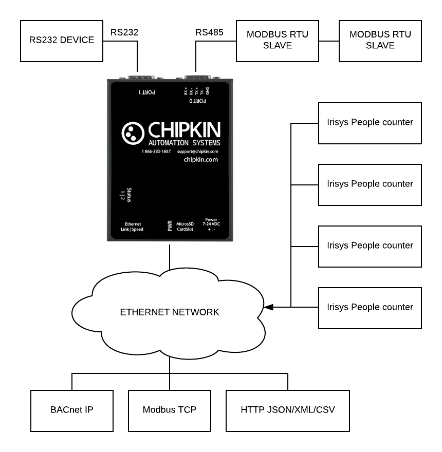
The Irisys people counter gateway can connect to one or more Irisys people counter devices and reads the current occupancy data from the device.
The occupancy read by
various other protocols including BACnet IP, Modbus TCP, Modbus RTU or web protocols. The gateway supports all these options simultaneously. Use the data you want and ignore the other.
The Gateway requires minimal configuration and can be considered a plug and play component of a system.
A series of BACnet objects will be created when a new sensor to the CAS Gateway.
- device: 389001 (PeopleCounter)
- analog_input: 1 (West Building - Occupancy)
- analog_input: 2 (West Building:Ground floor - Occupancy)
- analog_input: 3 (West Building:Ground floor:Main Entrance - Count In)
- analog_input: 4 (West Building:Ground floor:Main Entrance - Count Out)
- analog_input: 5 (West Building:Ground floor:Main Entrance - Occupancy)
- analog_input: 6 (West Building:Ground floor:Main Entrance - Normalized Occupancy)
- analog_input: 7 (West Building:Ground floor:Main Entrance - Device In)
- analog_input: 8 (West Building:Ground floor:Main Entrance - Device Out)
- analog_input: 9 (West Building:Ground floor:Main Entrance - Reset)
Each building will have its own BACnet Occupancy object that is a sum of all the floors's Occupancy.
Each floor will have its own BACnet Occupancy object that is a sum of all the sensor’s occupancy values on that floor.
Each sensor will have several objects created
- Count In – The change in {device in} since the last reset hour.
- Count Out – The change in {device out} since the last reset hour.
- Occupancy – The difference between {count in} and {count out}
- Normalized Occupancy – The difference between {count in} and {count out} using the slope algorithm.
- Device In – The raw values read from the people counter device for the in line.
- Device Out – The raw values read from the people counter device for the out line.
- Reset – The difference between {Device in} and {Device out} at the time of the reset hour.
CAS Hardware 700
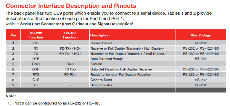
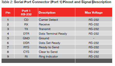
The CAS 700 Hardware device contains 2x 9-pin serial ports (1x RS485 and 1xRS232), and one Ethernet port. The device also contains a microSD card where system files, assets, configurations, and logs are stored.
The device has the following system drivers that can be enabled:
- HTTP REST Server - a passive web server with an API that users can interact with the device to get or set values
- HTTP Push Driver - a driver that can be configured to push data in a specific format (JSON, XML, CSV) to a 3rd party web server. Current data formats are Chipkin's default JSON payload and VeederRoot Tank data as JSON. Please contact Chipkin for information on adding additional formats.
Irisys People Counter Driver
The Irisys people counter gateway can connect to one or more Irisys people counter devices and reads the current occupancy data from the device.
The occupancy read by various other protocols including BACnet IP, Modbus TCP, Modbus RTU or web protocols. The gateway supports all these options simultaneously. Use the data you want and ignore the other.
The Gateway requires minimal configuration and can be considered a plug and play component of a system.
A series of BACnet objects will be created when a new sensor to the CAS Gateway.
- device: 389001 (PeopleCounter)
- analog_input: 1 (West Building - Occupancy)
- analog_input: 2 (West Building:Ground floor - Occupancy)
- analog_input: 3 (West Building:Ground floor:Main Entrance - Count In)
- analog_input: 4 (West Building:Ground floor:Main Entrance - Count Out)
- analog_input: 5 (West Building:Ground floor:Main Entrance - Occupancy)
- analog_input: 6 (West Building:Ground floor:Main Entrance - Normalized Occupancy)
- analog_input: 7 (West Building:Ground floor:Main Entrance - Device In)
- analog_input: 8 (West Building:Ground floor:Main Entrance - Device Out)
- analog_input: 9 (West Building:Ground floor:Main Entrance - Reset)
Each building will have its own BACnet Occupancy object that is a sum of all the floors's Occupancy.
Each floor will have its own BACnet Occupancy object that is a sum of all the sensor’s occupancy values on that floor.
Each sensor will have several objects created
- Count In – The change in {device in} since the last reset hour.
- Count Out – The change in {device out} since the last reset hour.
- Occupancy – The difference between {count in} and {count out}
- Normalized Occupancy – The difference between {count in} and {count out} using the slope algorithm.
- Device In – The raw values read from the people counter device for the in line.
- Device Out – The raw values read from the people counter device for the out line.
- Reset – The difference between {Device in} and {Device out} at the time of the reset hour.
Modbus RTU Driver
The CAS Modbus RTU driver allows the CAS Gateway to transfer data to and from devices via a serial RS485 connection using the Modbus protocol. The CAS Gateway can either be a Client, reading and controlling values from a slave, or a Server, serving data to a Modbus Master.
The CAS Modbus RTU Driver supports the following Modbus Functions:
| - 01 (0x01) Read Coils | - 05 (0x05) Write Single Coil |
| - 02 (0x02) Read Discrete Inputs | - 06 (0x06) Write Single Register |
| - 03 (0x03) Read Holding Registers | - 15 (0x0F) Write Multiple Coils |
| - 04 (0x04) Read Input Registers | - 16 (0x10) Write Multiple Registers |
Modbus TCP Driver
The CAS Modbus TCP driver allows the CAS Gateway to transfer data to and from devices over Ethernet TCP/IP using the Modbus protocol. The CAS Gateway can either be a Client, reading and controlling values from a slave, or a Server, serving data to a Modbus Master.
The CAS Modbus TCP Driver supports the following Modbus Functions:
| - 01 (0x01) Read Coils | - 05 (0x05) Write Single Coil |
| - 02 (0x02) Read Discrete Inputs | - 06 (0x06) Write Single Register |
| - 03 (0x03) Read Holding Registers | - 15 (0x0F) Write Multiple Coils |
| - 04 (0x04) Read Input Registers | - 16 (0x10) Write Multiple Registers |
Specifications
The following specifications are common to all Chipkin gateways.
- Certifications: UL and ULc approved
- Ports:
- 10/100BASE-T with RJ-45 connector
- 1x RS232 port
- 1x RS485 port (different models have additional ports)
- Power: 7 - 24 VDC through an external power supply. (12V @ 90mA)
- Operating temperature: 0 - 70 °C (32 - 158 °F)
- LEDs: link, speed/data, power
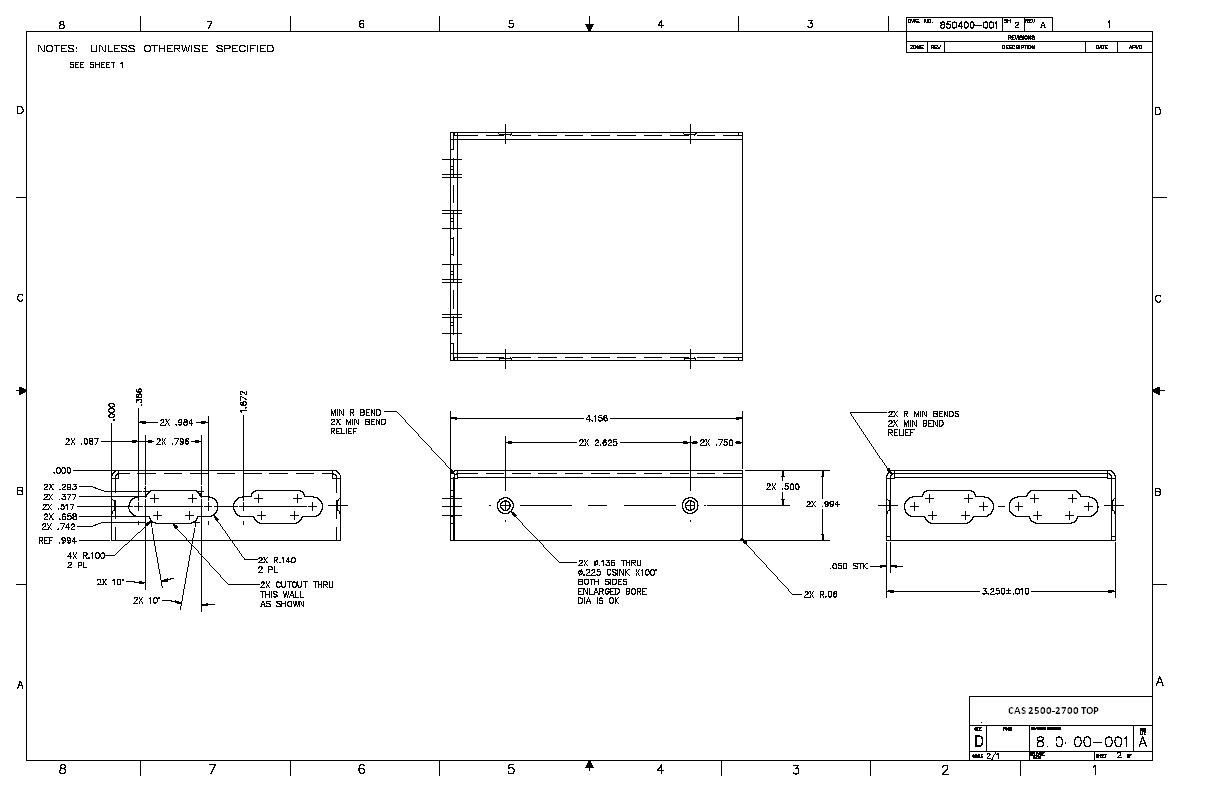
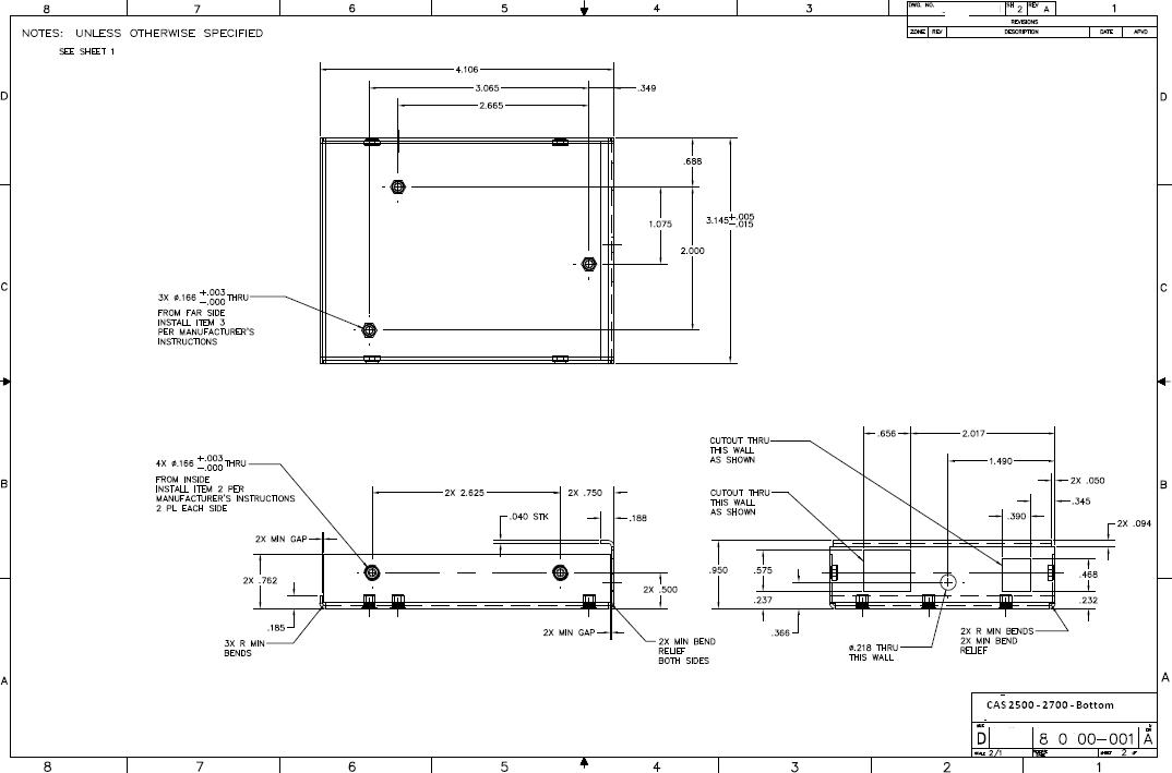
Dimensions
- Dimensions (LxWxH): 107 x 83 x 25 mm (4.2 x 3.25 x 1 in.)
- Connection type: RS485 (jumper change to RS232)
Top
Bottom
Tools
Resources
A quick start guide with instructions for some of the basic operations of the CAS Gateway product line. Includes instructions for the following:
- Detecting the CAS Gateway via the computer and settings its IP Address
- Downloading the Firmware to the CAS Gateway
- Downloading the Assets to the CAS Gateway
- Downloading the Configuration to the CAS Gateway
Additional Information
Irisys press release
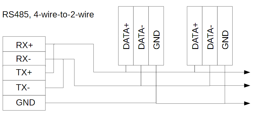
CAS 2500/2700 RS485 Connector
