EST3 - What is the purpose of the Edwards QuickStart Serial driver
Driver Review: 1.03
Document Revision: 0
FieldServer Driver - Serial
FS-8700-93
Edwards Systems Technology - QuickStart
Description
The QuickStart Serial driver allows the FieldServer to record data from Edwards System Technology QS1-2/4-8 and QSC Fire Panels over the RS-232 printer port. The FieldServer acts as a Passive Client receiving messages and updating its internal data arrays which records the status of devices connected to the QuickStart fire alarm control panel. The QuickStart panels currently do not support duplexed communications; therefore, this driver has only been designed to listen for messages passively and not to respond or to generate polls.
The main purpose of this driver is to record the status of Fire Alarm System points in bit oriented data arrays. It is limited by the information that the QuickStart control panels broadcasts in the form of text messages through its RS-232 printer port.
The types of EST messages supported by this driver are listed later in this fact sheet and in the FieldServer Driver Manual. Device status to the data array mapping is also provided. Since there are a variety of optional cards that can be selected for each QuickStart installation, each FieldServer application must be specifically configured before use. FieldServer data storage arrays for panel status will be allocated according to the number and type of cards implemented. Message information will also be stored according to card and panel addressing.
This driver is connection oriented; therefore, only one EST Panel may be connected to any single RS-232 FieldServer port.
The driver currently accommodates European and American English Conventional/Intelligent panels using the American English protocol with provisions for using the British English protocol at a later date.
FieldServer Synchronization
To synchronize the FieldServer's data arrays with the QuickStart control panel's status, the panel must have no active or disabled points on FieldServer startup. Alternatively, a panel can be hard/soft restarted to clear all point status, and then re-annunciate any active devices after the FieldServer has been started. This should only be undertaken by qualified technicians.
Should the panel be soft restarted unexpectedly, the FieldServer will recognize the "restart" command and clear all internal data arrays. There will be no need for FieldServer restart; however, for a hard restart, the FieldServer data arrays should be manually cleared by changing a bit in the CLEAR_FLAG data array through RUINET, then soft restarting the panel again to ensure that status of all points is re-annunciated and recorded by the FieldServer.
Device States
Each addressable device (real or pseudo) can have multiple states: alarm supervisory, monitor, other (security), and troubles. These states are not exclusive; therefore, a single addressable point may occupy multiple states at the same time.
Although there may be several trouble states for each device, there can only be a single alarm, supervisory, monitor and other (security) state per address. Therefore any restoring messages for these four states indicate that the device is clear of any active problems for these types of conditions.
However, there may be several trouble states for a single addressable port. These trouble states will be recorded in a separate trouble array of 2 byte elements. Each array element will correspond to a device address and each bit within the element will correspond to a trouble type. The mapping of message trouble types to element bit configuration is given below. For modeling simplicity and flexibility, it is assumed that all addressable points (real or pseudo) can exist in all states.
Formal Driver Type
Serial
Passive Client
Compatibility Matrix
| FieldServer Model | Compatible with this driver |
| FS-x2010 | Yes |
| FS-x2011 | Yes |
| FS-x40 | Yes |
| FS-x30 | No |
| FS-x30 | Yes, No |
Connection Information
| Connection type: | RS-232 (Simplex) |
| Baud Rates: | 9600 (Vendor limitation) |
| Data Bits: | 8 (Vendor limitation) |
| Stop Bits: | 1 (Vendor limitation) |
| Parity: | None (Vendor limitation) |
| Multidrop Capability | No |
Devices tested
| Device | Tested (FACTORY, SITE) |
| Edwards Systems Technology - European and American QS1-2/QS4-8 Addressable Panels, and the QSC Conventional Panel | SITE |
Connection configurations
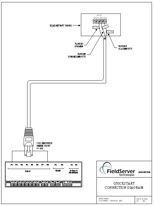
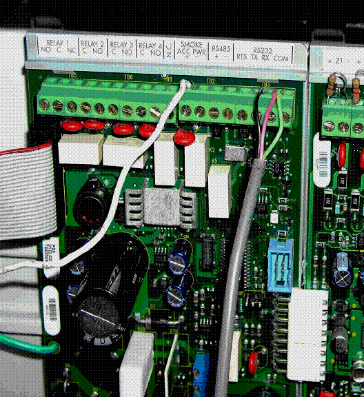
The FieldServer is connected to the EST QuickStart power supply card as shown below. Configure the EST QuickStart panel according to manufacturer's instructions.
Connection Notes
The QuickStart panels must be pre-configured using their own proprietary configuration tool to send messages to the RS-232 printer port. Ensure that this is done before attempting to connect to the FieldServer and verify that messages are being sent using a utility like Hyperterminal.
Bit Map of Trouble States for 2 Byte Array Elements
| Message Type | State | Bit/UINT16/Packed Bit |
| TROUBLE OPEN |
TBL OPEN RSTT0TROUBLE SHRT
TBL SHRT RSTT1LCL TROUBLE
LCL TRBL RSTT2DIRTY HEAD
DTY HEAD RSTT3COMMN FAULT
COMM FLT RSTT4GROUND FAULT
GND FLT RSTT5INTERNAL TBL
INTR TRBL RST6BAD TYPE
BAD TYPE RSTT7BAD PRSONATY
BAD PRSTY RST8UNEPECT DEV
UNEC DEV RSTT9TROUBLE
TROUBLE RSTT10TEST
TEST RSTT11DEV COMPATBL
DEV COMP RSTT12SERVICE GRP
SERVICE G RST13DISABLED
DISABLED RSTT14DISAB SOUND
DISSOUND RSTT15
Device Addressing
The following table defines the address space expected by the driver for each type of card. The table includes both physical and pseudo points used by the QuickStart systems.
|
Panel |
Card |
Address |
Card Type |
|
| Point Addressing | 0 |
0
0
0
0
0
0
1
2
3
4
5
6
7
8
9
1
1
1
1
1
1
10
17
18
19
20
21
22
0
0
0
0
0
0
0
0
0
01-07
01-07
01-13
01-13
01-13
14
150-18 (49)
0-480 (499)
0-64 (99)
0-64 (99)
0-128 (199)
0-32 (49)
0-250 (499)
0-32 (49)
0-33 (49)
0-33 (49)
0-33 (49)
0-33 (49)
0-33 (49)
0-33 (49)
0-33 (49)
0-33 (49)
0-341 (499)
0-275 (499)
0-19 (49)
0-11 (49)
0-11 (49)
0-16 (49)
0-24 (49)pseudo points
zone
AND group
matrix group
service group
time control
output group
CPU (reserved)
annunciator
annunciator
annunciator
annunciator
annunciator
annunciator
annunciator
annunciator
ADC
SLIC
Class B (ZA16-8)
Class A (ZA8-2)
Relay (ZR-8)
Dialer (DLD)
Power (PS6)
Data Array Memory Allocation
Each QuickStart card (real and pseudo) is configured with BIT and UINT16 or Packed Bit data arrays. The following states are recorded in the BIT array.
1. Alarms
2. Supervisory
3. Monitor
4. Other (security)
Alarms will be stored in the first quarter of the array; Supervisory conditions will be stored in the second quarter etc. according to the above ordering.
Troubles are recorded in a separate array of UINT16 or packed bit elements. Each element represents a uniquely addressable point, and each bit within the element represents a different type of trouble condition which is described by the specific trouble message.
The following two tables list the BIT and UINT16/Packed_Bit data array sizes that should be configured for every panel by default, and arrays for each optionally installed card. The data arrays configured for all QuickStart panels are for cards (real and pseudo) which always have fixed card addresses. Not all of these default data arrays will be utilized for every installation. Optionally installed cards can have variable card ID numbers depending on the sequence the cards are installed.
Data arrays are referenced relatively according to their declared size. Therefore, care must be taken to ensure that the array sizes are configured as noted in the tables.
Data Storage Requirements for Every Panel
| Card/Array Descriptions | Array Size | Data Type |
| Pseudo points | 200 | BIT |
| Pseudo point troubles | 50 | UINT16/Packed_Bit |
| Zones | 2000 | BIT |
| Zone troubles | 500 | UINT16/Packed_Bit |
| AND group | 400 | BIT |
| AND group troubles | 100 | UINT16/Packed_Bit |
| Matrix group | 400 | BIT |
| Matrix group troubles | 100 | UINT16/Packed_Bit |
| Service group | 800 | BIT |
| Service group troubles | 200 | UINT16/Packed_Bit |
| Time control | 200 | BIT |
| Time control troubles | 50 | UINT16/Packed_Bit |
| Output group | 2000 | BIT |
| Output group troubles | 500 | UINT16/Packed_Bit |
| CPU reserved | 200 | BIT |
| CPU reserved troubles | 50 | UINT16/Packed_Bit |
| Power card | 200 | BIT |
| Power card troubles | 50 | UINT16/Packed_Bit |
Data Storage Requirements for Optional Cards
| Card/Array Descriptions | Array Size | Data Type |
| ADC (dual loop) | 2000 | BIT |
| ADC (dual loop) troubles | 500 | UINT16/Packed_Bit |
| SLIC | 2000 | BIT |
| SLIC troubles | 500 | UINT16/Packed_Bit |
| Class A card | 200 | BIT |
| Class A card troubles | 50 | UINT16/Packed_Bit |
| Class B card | 200 | BIT |
| Class B card troubles | 50 | UINT16/Packed_Bit |
| Relay card | 200 | BIT |
| Relay card troubles | 50 | UINT16/Packed_Bit |
| Annunciator (per card) | 200 | BIT |
| Annunciator troubles (per card) | 50 | UINT16/Packed_Bit |
| Dialer | 200 | BIT |
| Dialer troubles | 50 | UINT16/Packed_Bit |
Message Types Supported
The primary purpose of this driver is to record the status of devices connected to the QuickStart Fire Control Panel by interpreting the text messages sent to its printer port. Not all messages will be interpreted, as many messages and reports do not directly affect device status. The following set of events and messages will be recognized and recorded in the data arrays.
| A. Event Description Text Strings | State | Comments |
| ACTIVATE RESTART | -OPERATOR COMMAND- clears all the data arrays | |
| QUIESCENT |
QUIE RST Not ImplementedALARM ACTIVE
ALARM RSTA PULL STATION
PULL STA RSTA HEAT ALARM
HEAT ALM RSA WATERFLOW
WATERFLOW RSA STAGE ONE
STAGE ONE RSA SUPERVISORY
SUP RSTS TAMPER
TAMPER RSTS SECURITY
SECURITY RSTO FIREPHONE
PHONE RSTM MONITOR
MONITOR RSTM LATCH SUPV
LAT SUPV RSTS LATCH TAMPER
LAT TAMP RSTS UNKNOWN
UNKNOWN RSTO ALARM VERIFY
ALM VFY RSTM PREALARM
PREALARM RSTM TROUBLE OPEN
TBL OPEN RSTT TROUBLE SHRT
TBL SHRT RSTT LCL TROUBLE
LCL TRBL RSTT MAINT ALERT
MAT ALERT RSM DIRTY HEAD
DTY HEAD RSTT COMMN FAULT
COMM FLT RSTT GROUND FAULT
GND FLT RSTT INTERNAL TBL
INTR TRBL RST BAD TYPE
BAD TYPE RSTT BAD PRSONATY
BAD PRSTY RST UNEPECT DEV
UNEC DEV RSTT TROUBLE
TROUBLE RSTT RELAY CONFIR
RLY CFRM RSTM LCL MONITOR
LCL MNTR RSTM SWITCH
SWITCH RSTM TEST
TEST RSTT DEV COMPATBL
DEV COMP RSTT AND GROUP
AND GRP RSTA MATRIX GROUP
MATRIX G RSTA SERVICE GRP
SERVICE G RST TIME CONTROL
TIME CNTL RSM ACK
ACK RSTM DISABLED
DISABLED RSTT DISAB SOUND
DISSOUND RSTT OBJECT RUN
OBJETRUN RSTM ZONE ALARM
ZONE ALM RSTA ZONE SUPER
ZONE SUP RSTS ZONE MONITOR
ZONE MON RSTM OUTPUT GROUP
OUTPUT G RSTM AUDIBLE
AUDIBLE RSTM VISUAL
VISUAL RSTM SUPER OUTPUT
SUPER OUT RTM NONSUPER OUT
NONSUP OUT RM COMM ALM OUT
COMMALOUTRSTM LED OUTPUT
LEDOUTPU RSTM
FieldServer Limitations & Exclusions
- · Only one QuickStart panel may be connected to any given RS-232 port at once.
- · QuickStart and FieldServer synchronization requires some manual steps. This is described in the section of this fact sheet called "FieldServer Synchronization".
- · This driver cannot poll for data, thus if a message sent by the panel is lost or corrupted the status reported by the FieldServer will not correctly reflect the status of the panel until the panel is synchronized again or until the FieldServer receives a new message reporting the status of the lost message's point.
- · Because of the message structure for the QuickStart protocol, it was intended to be the only protocol assigned to any single port.
THIS PAGE INTENTIONALLY LEFT BLANK

