Classic QuickServer Gateway (KNX)
Sierra Monitor is a leader in protocol gateways for the building automation industry, enabling system integrators and developers to prepare building automation and process control infrastructures for the future by breaking down protocol barriers.
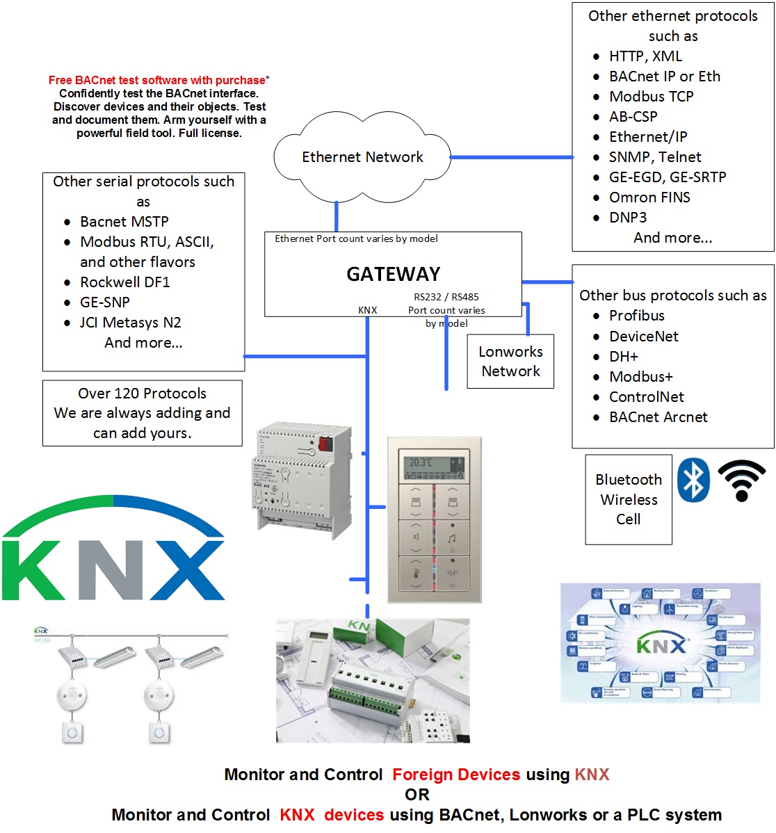
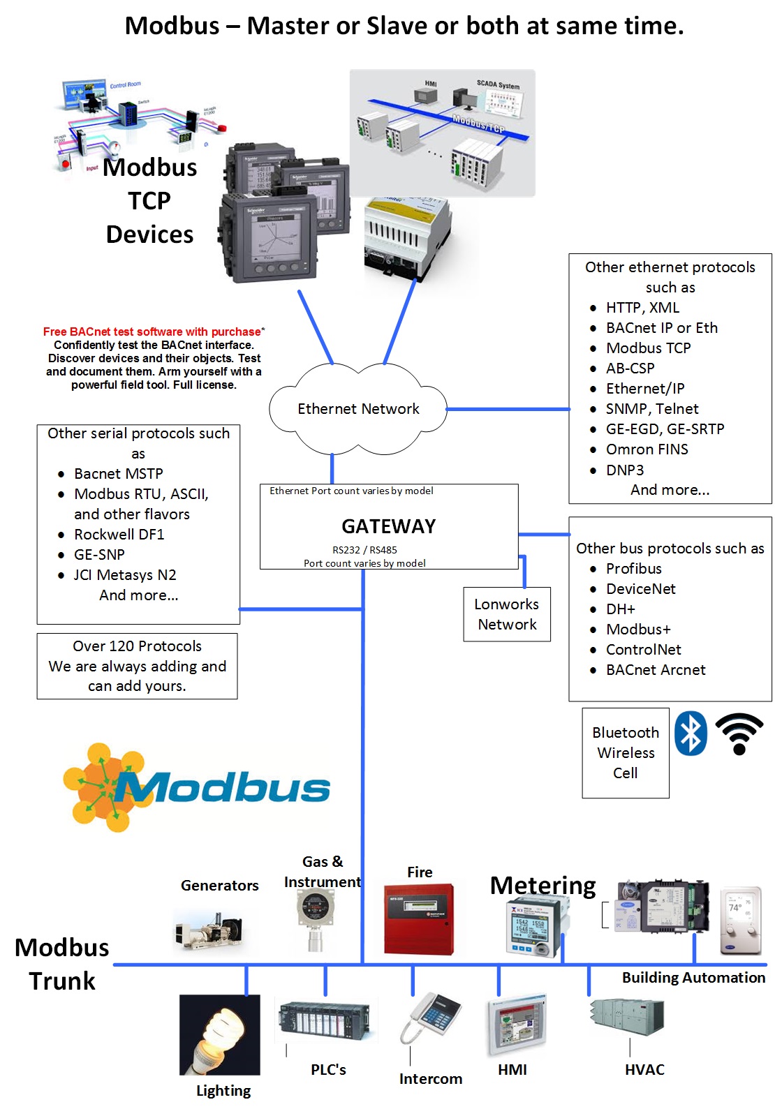
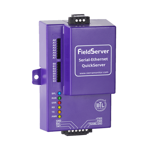
With the QuickServer KNX Gateway, FieldServer enables data access from KNX networks to devices and networks utilizing open and proprietary protocols such as BACnet, Modbus, LonWorks, Metasys N2 by JCI, SNMP and more. With over 100 protocols available in the extensive FieldServer Driver Library, no other product can connect KNX to more products!
FieldServer is in thousands of installations with over 700 translation paths. These gateways are LonMark certified, BACnet compliant, Metasys N2 compatible and mission-critical tested.
QuickServer is a galvanic-isolated translator device on KNX/TP installations with control and monitoring capabilities. All EIS data types are supported, allowing communication to any kind of KNX devices in the installation, such as temperature sensors, shutters, light switches, actuators, alarms etc.
Each QuickServer includes browser-based tools to make it easy to set-up QuickServer and perform diagnostics including determination of status, network settings, node information, map descriptors and more. The USB flash drive also includes the Discovery utility to determine what FieldServers are on a network.
Modbus TCP
The Modbus TCP Driver allows the FieldServer to transfer data to and from devices over Ethernet using Modbus TCP Protocol. The Modbus TCP driver uses port 502. This port is not configurable. The driver was developed for Modbus Application Protocol Specification V1.1a" from Modbus-IDA. The specification can be found at www.modbus.org. The FieldServer can emulate both a Client and a Server simultaneously on the same ethernet port.
There are various register mapping models being followed by various vendors. To cover all these models FieldServer uses the following three Models
- Modicon_5digit – Use this format where addresses are defined in 0xxxx, 1xxxx, 3xxxx or 4xxxx format. A maximum of 9999 registers can be mapped of each type. This is FieldServer driver’s default format.
- ADU –Application Data Unit address. Use this format where addresses of each type are defined in the range 1-65536
- PDU –Protocol Data unit address. Use this format where addresses of each type are defined in the range 0-65535.
The key difference between ADU and PDU is for example if Address_Type is ADU and address is 1, the driver will poll for register 0. If Address_Type is PDU, the driver will poll for address 1.
Note 1: If vendor document shows addresses in extended Modicon (i.e. 6 digit) format like 4xxxxx then consider these addresses as xxxxx (omit the first digit) and use either ADU or PDU
Note 2: The purpose of providing 3 different ways of addressing the Modbus registers is to allow the user to choose the addressing system most compatible with the address list being used. At the protocol level, the same protocol specification is used for all three with the exception of the limited address range for Modicon_5digit.
KNX
The KNX driver allows the FieldServer to transfer data to and from devices using KNX protocol. The Fieldbus connection is included with the FieldServer. The FieldServer can emulate a Passive Client.
The KNX driver enables data access from KNX networks to other FieldServer protocols. Most KNX data point types are supported, allowing communication to almost any kind of KNX device in the installation, such as temperature sensors, shutters, light switches, actuators, alarms etc. This allows BMS systems to access a KNX network using direct read and write of KNX configured groups. This setup does not require the use of ETS4 to configure the QuickServer KNX gateway.
The KNX protocol is a connectionless protocol and therefore supports multiple clients and multiple servers.
The QuickServer is intended to act as a Passive
Client on the KNX bus and make information
available to other protocols.
Specifications
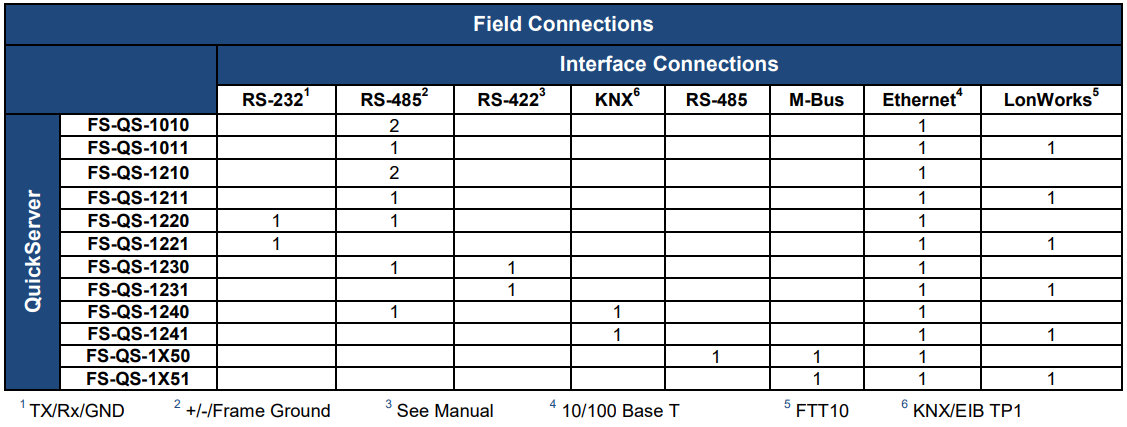
Classic QuickServer Specs: FS-QS-1X4X
Depending on what hardware you require, the specifications will contain different options..

Environment
- Operating Temperature: -40 to 75°C (-40 to 167°F)
- Relative Humidity: 5-90% RH non-condensing
Power Requirements
9-30V DC or 12-24V AC
(RS-422 = 15-30V DC or 12-24V AC)
(M-Bus = 12-24V DC)
Current draw: @ 12V
- FS-QS-1010, FS-QS-1210, FS-QS-1220: 240 mA
Physical Dimensions
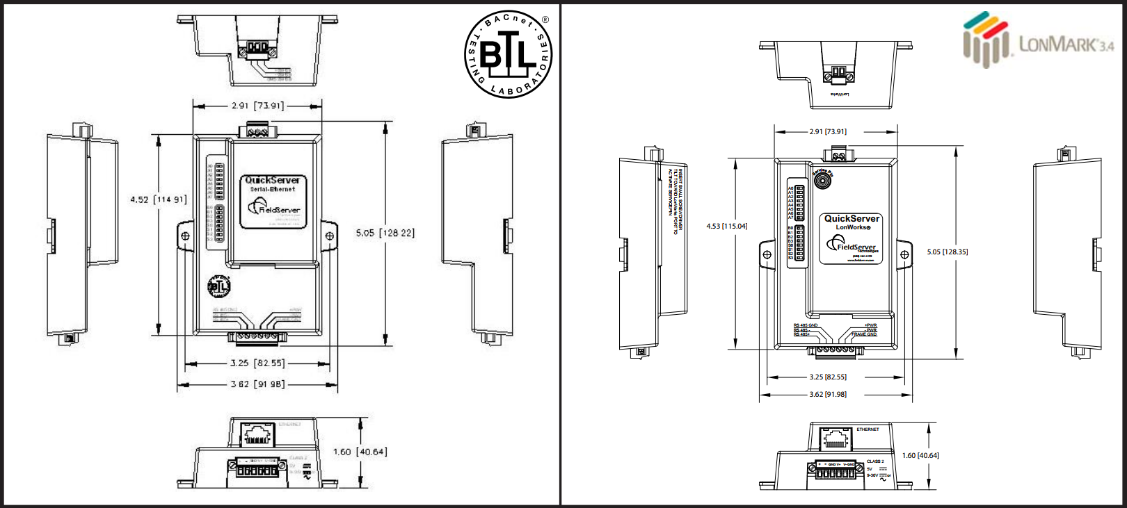
- Dimensions (WxDxH): 4.5x2.9x1.6 in. (11.5x7.4x4.1cm
- Weight: 0.4 lbs (0.2 Kg)
- Input voltage: 24 V DC nominal: 10-30V DC
Other
Configuration/Diagnostic utilities
- Capacity: 250 points (FS-QS-104X), 500 points (FS-QS-124X), 3000 Points (FS-QS-134X), 5000 Points (FS-QS-144X)
- Table, Wall or DIN rail mount
Communication
- Baud: 4800, 9600, 19200, 38400, 57600, 115200
- Start Bit: 7, 8
- Stop Bit: 1, 2
- Parity: Even, Odd, None
LonMark Certification on the QuickServer FS-QS-1XX1-XXX
- SPID: 80:00:95:46:00:84:04:01
- Profiles: 0000 - Node object (1), 0001 - Open Loop Sensor Object (5), 0003 - Open Loop Actuator Object (5)
- Ethernet: 1, 2
- Parity: 10/100 BaseT
Approvals
- TUV Approved: to UL 916, EN 60950-1, EN 50491-3 and CSA C22.2 standards
- BTL Mark:
- LonMark Certified: (FS-QS-1011 and FS-QS-12X1)
- RoHS Compliant
- GOST-R Certified
- CE and FCC

Dimensions
Resources
Additional Information
Modbus - MK10 and 32 Bits Numbers
Scaling in Modbus
Modbus does not provide a method for transporting large or Floating Point numbers or a mechanism for scaling analog values. A 16 bit word can only contain values in the range 0-65535. Only whole numbers are permitted. To work around this many server device manufacturers use multipliers and document them in their manuals. For example, to report a temperature of 58.5 the device reports a value of 585, and makes a note in the manual that the master should scale by 10. This scaling is achieved by adopting a convention between the client and the server.
What about large numbers > 65535
Modbus does not provide a mechanism but 3 important schemes are widely used.
Long Integers – Two consecutive 16 bit words are interpreted as a 32 bit long integer.
MK10 values – Two consecutive words are used. The 1st reports the number of units and the 2nd reports the number of 10,000’s.
Floating Point Numbers – Two consecutive words are used and a scheme. These schemes are conventions and not all servers or clients support them.
The protocol does not identify these big numbers. Only the vendor docs do.
What we mean by this is – if you look at the byte stream in a Modbus message there is no way of telling whether you are looking at two consecutive 16 bit words, or two consecutive words that should be interpreted as floating point, long or MK10 formats. Because of this you always have to look to the vendor docs.
Modbus - Reading Vendor Modbus Maps
Reading Vendor Modbus Maps
If you are reading the documentation for sensor blocks, valves, and other devices, you must keep in mind that some vendors may document their hardware in different ways.
According to the Modbus standard, addresses are simply integers from 0 to 65,535 with the different address ranges being referred to as coils, holding registers, etc. However, some vendors will document their hardware using numerical prefixes which are not actually part of the Modbus address. This originated from some models of PLCs which used the Modbus communications protocol, and which also used numerical prefixes in their internal data table. This is similar to using “I”, “Q”, “V”, etc. as address prefixes in IEC type PLCs.
However, it is important to remember that these numerical prefixes are documentation methods and are not part of what the Modbus protocol itself sends as part of the messages. A difference in documentation methods does not affect the compatibility of the protocol itself.
These prefixes are they mentioned anywhere in the Modbus standard, but the following shows how they are typically used in documentation based on this older convention:
- 0xxxx – Coils.
- 1xxxx – Discrete inputs.
- 3xxxx – Input registers.
- 4xxxx – Holding registers.
Note that there is no 2xxxx address prefix.
In addition to numerical prefixes, some documentation will refer to protocol addresses (addresses start at 0), while other documentation will refer to data model addresses (addresses start at 1). That is, the first holding register may be 0 or 1 (or 40000 versus 40001 using prefixes). However, this has no bearing on what gets sent over the wire as a Modbus message. For a Modbus protocol message, the lowest address is always “0”, not “1”.
Modbus - Protocol Specifications
Protocol Specifications
Modbus - Flavors of Modbus
Flavors of Modbus
RTU:
Common
Binary Protocol.
Active Master-passive Slave
Serial
Supported by FieldServers, QuickServers, CAS gateways
ASCII:
Similar to ModbusRTU but for each byte in an RTU message, there are 2 bytes in an ASCII message. The 2 bytes are the humand readable form of the single hex byte.
Eg RTU byte = 0x03 (Hex). ASCII bytes = ‘0’ and ‘3’ ie 0x30 and 0x33
Active Master-passive Slave
Serial
Supported by FieldServers, QuickServers
Jbus:
Modbus had the limitation of a max of 9999 items of each type. Ie only 9999 holding registers. However the protocol message allows 65k items to be addressed. JBUS allows all 65k items to be read/written. Other than that it is identical to RTU
Active Master-passive Slave
Serial
Supported by FieldServers, QuickServers, CAS gateways
TCP/IP:
Uses TCP/IP connection based Ethernet communications
Encapsulates RTU messages and adds a header.
A single slave can respond to multiple masters
Many slaves ignore the NodeID field in the message.
Supported by FieldServers, QuickServers, CAS gateways
MB Plus:
Proprietary coax networking layer
2 Mbits/sec
Supported by FieldServers, CAS gateways
Logos


__68475.1769555204.png?c=2)
