KNX Topology a 10-Minute Course
KNX Protocol - 10-Minute Course
- KNX systems can be installed at required places and can consist of several KNX subsystems.
- It follows a tree topology.
- Nodes (N) are assigned to a line (L)
- Several lines are connected via a main line (ML) and form an area (A)
- Several areas are connected with each other via the backbone line (BL)
- The basic unit of a KNX TP installation is a line which includes a KNX power supply (including choke), and usually no more than 64 other bus devices.
- Branches could be taken out on bus cable to extend more subsystems.
- No more than three repeaters can be operated in parallel in a line, meaning the maximum number of bus devices is 255.
- Line Couplers could be used to increase the network further, up to 15 lines can be operated via Line Couplers on a line.
Cable Length:
- Distance from power supply to device: max. 350 m
- Distance between any two devices in a line: max. 700 m
- Length of a line segment: max. 1,000 m
- Distance between two power supplies (including choke) in a line: as per manufacturers' specifications.
Individual Address:
- Every device in a KNX system is assigned a unique, unambiguous number. This consists of three numbers separated by dots. The numbers depend on the position of the bus device in the topology:
- The first number denotes the number of the area
- The second number denotes the number of the line
- The third number is a sequential number indicating the device's position in the line
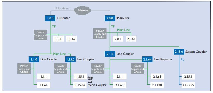
Fig: Example of KNX topology incorporating all media (TP, PL, RF, IP)


