Enhancing Industrial Communication: Profibus DP Connections
General Connectors Overview
Profibus DP Physical Layer and Connector Context
PROFIBUS DP (Decentralized Peripherals) is a widely deployed fieldbus in industrial automation for cyclic I/O and device communication between controllers (typically DP masters such as PLCs) and distributed field devices (DP slaves such as remote I/O, drives, valves, and instrumentation). While PROFIBUS defines the data link and application behavior, the reliability of a PROFIBUS DP segment is frequently determined by the physical layer: cable type, shielding practices, network topology, termination, and connector implementation.
Most PROFIBUS DP installations use RS-485 signaling over a shielded twisted-pair cable with defined impedance characteristics. Connector assemblies commonly incorporate multiple functions: (1) a mechanically stable connection to the device port, (2) consistent connection of shield/drain to maintain EMC performance, (3) a pass-through for the trunk cable, and (4) an integrated termination network that can be enabled/disabled depending on segment location. In practice, the connector is not just “a plug”; it is often the point where wiring quality, strain relief, and termination correctness are either enforced or compromised.
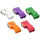
PROFIBUS DP connectors are produced by multiple manufacturers and are available in different angles and mechanical styles (e.g., 35°, 45°, 90°, 180°) to accommodate cabinet clearance, cable routing constraints, and service access. Many connector families are rated for up to 12 Mbps (the maximum for classic PROFIBUS DP over RS-485). Intrinsically safe variants (e.g., RS-485-IS) operate at lower data rates (commonly 1.5 Mbps) due to energy-limiting design constraints.
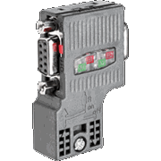
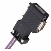
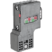
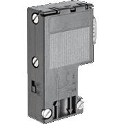
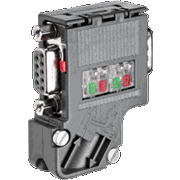
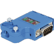
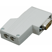
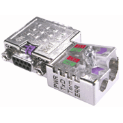
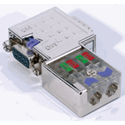
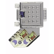
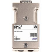
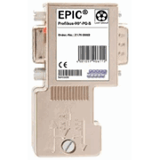
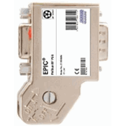
Explore the table below to see examples of PROFIBUS DP connector types and common form factors. The images highlight typical industrial “D-sub style” PROFIBUS connectors used in cabinets and on field devices, as well as variants that integrate PG (cable gland) features and/or diagnostic capabilities.
|
Profibus DP |
||
|
Type |
Baud rate |
|
|
ProfiConnector Plug Cage Clamp |
12 Mbps |
|
|
ProfiConnector Plug Cage Clamp & PG |
12 Mbps |
|
|
ProfiConnector Plug Screw |
12 Mbps |
|
|
ProfiConnector Plug Screw & PG |
12 Mbps |
|
|
PROFIBUS DP IP 20 FC Connector (180°) |
12 Mbps |
|
|
PROFIBUS DP IP 20 FC PG Connector (90°) |
12 Mbps |
|
|
PROFIBUS DP IP 20 PG Connector (90°) |
12 Mbps |
|
|
PROFIBUS DP IP 20 FC Connector (90°) |
12 Mbps |
|
|
PROFIBUS DP IP 20 Connector (90°) |
12 Mbps |
|
PROFIBUS DP IP 20 FC PG Connector (35°) |
12 Mbps |
|
|
PROFIBUS RS 485-IS connector (35°) |
1.5 Mbps |
|
|
PROFIBUS DP IP 20 Connector (90°) |
12 Mbps |
|
|
PROFIBUS DP Diagnostic FC Connector (180°) |
12 Mbps |
|
|
PROFIBUS DP Diagnostic FC PG Connector (90°) |
12 Mbps |
|
|
PROFIBUS DP FC PG Connector (90°) |
12 Mbps |
|
|
PROFIBUS DP Diagnostic FC PG Connector (45°) |
12 Mbps |
|
|
PROFIBUS DP IP 20 Connector (180°) |
12 Mbps |
|
|
PROFIBUS DP IP 20 FC PG Connector (90°) |
12 Mbps |
|
|
PROFIBUS DP IP 20 PG Connector (90°) |
12 Mbps |
|
|
PROFIBUS DP IP 20 PG Connector (35°) |
12 Mbps |
|
Termination, Shielding, and Topology Considerations
PROFIBUS DP over RS-485 is typically wired as a linear bus (daisy chain) with termination required at both ends of the segment. Many PROFIBUS connectors include a termination switch that inserts the termination network when enabled. This is convenient, but it also introduces a common field failure mode: a termination switch left in the wrong position, or a connector replaced without preserving the prior switch setting. As a rule, only the two end devices on a segment should have termination enabled (and those end devices must be powered if their termination is active in the connector design).
Shielding and bonding practices are equally important. PROFIBUS cable is designed with a shield (often braided and/or foil) to improve EMC performance. Many connector styles provide a dedicated clamp or contact surface to bond the shield to the connector housing. A consistent shield termination approach (and avoiding “pigtails” where possible) helps reduce susceptibility to noise, particularly in environments with VFDs, large motors, contactors, and welding equipment.
Mechanical angle options (35°, 45°, 90°, 180°) exist primarily to reduce stress on the cable and to fit within cabinet clearances. In dense control panels, right-angle connectors can prevent excessive bend radius at the device port. In field housings where service access is limited, a 35° or 45° connector can improve cable routing without forcing the cable into a tight bend immediately at the connector exit.
- End-of-line devices: confirm termination is enabled and physically located at the two segment ends.
- Mid-segment devices: termination should be disabled; connector must support pass-through wiring.
- Shield bonding: clamp/bond as designed; maintain continuity through the segment.
- Strain relief: use PG glands or mechanical retention where movement/vibration is expected.
Commissioning and Troubleshooting Notes
When a PROFIBUS DP network experiences intermittent faults, the root cause is frequently physical-layer related rather than protocol-level. Typical symptoms include devices intermittently dropping off the bus, sporadic diagnostic alarms, and communication that degrades as additional nodes come online. A structured troubleshooting approach will usually converge faster than trial-and-error device replacement.
Practical checks that often resolve issues:
- Verify the segment topology (linear bus) and that any stubs are within vendor recommendations.
- Confirm termination is enabled only at the two ends and that end devices providing termination are powered.
- Inspect each connector for correct shield clamp contact and proper conductor seating (no loose strands).
- Confirm cable routing minimizes parallel runs with high-power conductors, and maintains separation where possible.
- Validate the configured baud rate is compatible across devices and matches the network configuration.
Diagnostic connector variants can be useful during commissioning because they provide a convenient point to measure or monitor the bus without disturbing the installed wiring. Regardless of connector type, documenting the physical segment (device order, termination locations, and connector angles) is a low-effort step that reduces downtime when future service work occurs.
Frequently Asked Questions (FAQ)
Q1: Why do many PROFIBUS DP connectors include a termination switch?
The termination switch inserts the required end-of-line termination network into the segment when the device is located at the end of the bus. This simplifies installation, but it must be set correctly. If termination is enabled at a mid-segment device (or missing at an end device), reflections and signal integrity issues can occur.
Q2: Do I need termination to work if the bus is short?
Even short segments can exhibit reflections and intermittent behavior without correct termination, especially at higher baud rates and in noisy industrial environments. Proper termination at both ends is standard practice and should not be skipped.
Q3: What do the connector angles (35°, 45°, 90°, 180°) change electrically?
Typically nothing electrical—these angles are primarily mechanical. They help route the cable within a cabinet or enclosure while preserving bend radius and reducing strain at the device port.
Q4: What is the difference between standard PROFIBUS DP and PROFIBUS RS-485-IS connectors?
RS-485-IS refers to intrinsically safe PROFIBUS designs intended for hazardous areas. Intrinsically safe implementations have energy limitations and commonly operate at reduced data rates (often 1.5 Mbps). Hardware (including connectors) must match the IS design requirements.
Q5: Why does a PROFIBUS segment sometimes fail after replacing a connector?
Common causes include incorrect termination switch position, loss of shield bonding due to improper clamp installation, conductor seating errors, or using a connector variant not intended for the cable diameter/PG gland requirements. After replacement, re-verify termination settings and shield continuity.