BNC Bayonet Neill-Concelman
General Connectors Overview
- VGA Video Graphics Array
- DVI Digital Visual Interface
- HDMI High-Definition Multimedia Interface
- Apple Dock Connector
- BNC Bayonet Neill-Concelman
- Fiber Connectors
- Controlnet Taps
- Devicenet Connectors
- Profibus DP
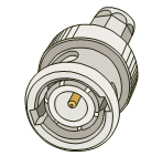
BNC Connector Fundamentals
The BNC (Bayonet Neill–Concelman) connector is a quick connect/disconnect radio-frequency connector used for coaxial cable. The defining mechanical characteristic is the bayonet coupling: the connector locks with a quarter-turn twist rather than a threaded coupling. This makes BNC suitable for applications where field technicians need fast connection changes, where cables are frequently moved, or where repeated connect/disconnect cycles are expected. BNC is most commonly associated with older TVs/monitors and professional video equipment, but it remains widely deployed in industrial systems that use coaxial media for video, timing/synchronization, test instrumentation, and legacy communications.
In practical systems engineering terms, a BNC connection should be treated as a controlled-impedance coaxial interface. The connector is only one part of the signal path: performance also depends on the cable type, shielding quality, termination method, and the impedance matching of the connected equipment. BNC is typically used with 50 ohm or 75 ohm coaxial systems. The connector bodies can look very similar, but 50 ohm and 75 ohm connectors are not always interchangeable at high frequency. In low-frequency or short-run cases this may appear to “work,” but it can introduce reflections and signal integrity issues in more demanding installations.
Where BNC Shows Up in Industrial and Building Systems
While consumer video has largely migrated to HDMI and DisplayPort, BNC is still common in industrial settings for a few reasons: robust coax cable options, simple point-to-point wiring, and a large installed base of equipment. Typical use cases include:
- Analog CCTV and legacy security cameras (composite video over 75 ohm coax).
- Professional video and broadcast equipment (SDI variants often use BNC connectors).
- Test and measurement equipment (oscilloscopes, signal generators, frequency counters; commonly 50 ohm).
- Timing and synchronization signals (pulse, trigger, or reference signals distributed over coax).
- Video distribution within facilities where coax infrastructure already exists.
When BNC is present in a project, the integration questions are typically about the media characteristics rather than the connector itself: cable length, shielding and grounding, and the termination strategy. Coax can perform very well in electrically noisy environments when installed correctly, but it is also sensitive to improper termination and poor connector crimping/compression. For field work, connector installation quality is one of the most common contributors to intermittent faults.
Termination, Impedance, and Common Failure Modes
Many BNC-based signal paths require correct termination. For example, composite video distribution and some instrumentation signals are designed to be terminated at the receiving end (and only at the receiving end). A missing termination can cause reflections (ghosting in analog video, ringing in fast edges), while double termination can reduce amplitude and degrade signal-to-noise margin. In professional workflows, you will often see 75 ohm terminators used explicitly on unused ports or end-of-line devices to maintain system stability.
Common field issues include:
- Loose bayonet lock (connector not fully rotated into the locked position).
- Incorrect connector type for the cable (e.g., mismatch between RG-59 vs RG-6 cable and the connector kit).
- Improper crimp/compression resulting in intermittent shield contact.
- Impedance mismatch (50 ohm vs 75 ohm) in higher-frequency or longer-run applications.
- Ground loops or shielding problems when coax is bonded differently at each end of the system.
From a maintenance standpoint, BNC has an advantage: faults are often diagnosable with standard tools (continuity checks, impedance/termination verification, and in instrumentation environments, a scope). A disciplined approach—confirm cable type, connector type, termination, and then validate the signal at both ends—typically resolves the majority of issues.
The table below summarizes the connector and typical usage context.
|
BNC |
|
|
Info |
Function |
|
Video & Power - Analog & Digital |
|
|
Supported Resolutions |
|
|
Limited only by hardware |
|
|
Power |
|
|
|
|
|
Common Uses |
|
|
Older TVs/monitors |
|
|
Male |
|
|
Female |
|

Practical Notes for Installation and Servicing
For industrial deployments, BNC reliability usually comes down to installation details. Use the correct connector kit for the cable family (for example, RG-59 and RG-6 have different diameters and dielectric dimensions) and apply the recommended crimp/compression tooling for the connector type. Ensure the shield braid and foil (if present) make consistent contact with the connector body, and verify that the center conductor is properly seated.
When retrofitting or troubleshooting, it is worth documenting the system assumptions: whether the signal path is 50 ohm or 75 ohm, whether termination is expected at the receiving end, and whether there are splitters or distribution amplifiers in the path. This information reduces “trial and error” work and prevents repeated service calls caused by partial fixes that do not address the underlying impedance or termination condition.
In mixed-signal environments (control panels, MCC rooms, and mechanical spaces), pay attention to routing and bonding. Coaxial cable provides good shielding, but if two endpoints are bonded to different ground references, ground currents can still couple into the system. Where this is a concern, evaluate isolation strategies or ensure that the overall grounding approach is consistent with the facility’s electrical design.
Frequently Asked Questions (FAQ)
Q1: What does “bayonet” mean in the context of a BNC connector?
It refers to the locking mechanism. The connector mates and then locks with a short twist (typically a quarter turn). This makes it faster to connect and disconnect than threaded RF connectors, and it is less likely to loosen from minor cable movement when fully locked.
Q2: Are all BNC connectors the same impedance?
No. BNC is commonly used in both 50 ohm and 75 ohm systems. The connector and the cable should match the system impedance expectations, particularly for higher-frequency signals, long runs, or professional video formats.
Q3: Do I always need a terminator on BNC video lines?
Many coax-based video systems expect termination at the receiving end (often 75 ohm). Missing termination can cause reflections and visible artifacts in analog video. However, the correct answer depends on the specific equipment and distribution design (direct point-to-point, loop-through devices, or distribution amplifiers).
Q4: What are typical signs of a poo