In Depth Guide on Fiber Connectors
General Connectors Overview
- VGA Video Graphics Array
- DVI Digital Visual Interface
- HDMI High-Definition Multimedia Interface
- Apple Dock Connector
- BNC Bayonet Neill-Concelman
- Fiber Connectors
- Controlnet Taps
- Devicenet Connectors
- Profibus DP
Fiber Optic Connectors in Automation and Industrial Networks
Optical fiber connectors are used to connect/disconnect at the ends of fiber optic cables. Connectors are often assembled onto optical fiber in a supplier's manufacturing facility to meet specification requirements. In industrial automation and building systems, fiber is commonly selected when copper cabling becomes impractical due to distance, electromagnetic interference (EMI), ground potential differences, or bandwidth requirements. Fiber is also widely used in campus backbones, building-to-building links, control room uplinks, and equipment rooms where electrical isolation is a design goal.
From a systems engineering standpoint, fiber connectivity is defined by more than the connector style. A complete fiber link includes: (1) fiber type (single-mode vs multimode), (2) core/cladding size and wavelength range, (3) termination quality (end-face geometry, polish type, cleanliness), (4) connector interface and locking method, and (5) the active optics (transceivers, media converters, switches). Most “it works / it doesn’t work” problems in the field come down to mismatch (e.g., single-mode optics on multimode plant), contamination, or improper handling of patch cords and end faces.
Single-Mode vs Multimode: Practical Implications
Single-mode fiber (SMF) is typically used for long distances and higher link budgets. It supports long runs and is common for building-to-building, campus, and carrier-style telecom applications. Multimode fiber (MMF) is commonly used inside buildings and data centers for shorter distances, and it is frequently paired with cost-effective optics at common wavelengths (e.g., 850 nm). The connector family does not inherently dictate single-mode or multimode, but the end-face polish and the transceiver selection often align to one or the other.
If you are integrating industrial Ethernet over fiber (switch-to-switch, SFP uplinks, or media converters), the optics module type (SFP, SFP+, XFP) and its wavelength/laser type will dictate what fiber plant can be used and the maximum supported distance. The LC connector is dominant in SFP/SFP+ deployments due to its small form factor and support for high-density patching.
Connector Geometry, Polish, and Handling
Fiber connectors are precision mechanical interfaces. Alignment is achieved through ferrules and sleeves that position two fiber end faces with micrometer-level accuracy. The “loss” at a connector is largely driven by end-face condition (scratches, chips), contamination (dust, oils), and the polish style. While this page focuses on connector families, in field operations the single most important practice is cleanliness: inspect and clean before every mating. A contaminated end face can introduce significant insertion loss and reflections, and it can permanently damage the fiber end when mated under pressure.
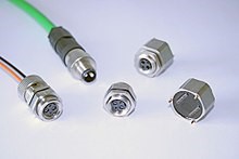
For industrial panels and plant floors, the mechanical environment also matters. Vibration, dust, and frequent maintenance access are common. Ruggedized connector options and sealed housings are used where standard patching hardware is not appropriate. M12 fiber connectors are one example used in machine, process, and plant engineering, typically chosen when a circular, robust, and environmentally tolerant interface is required.
Connector Families and Typical Applications
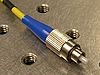
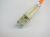
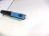
The table below summarizes several common fiber connector types, including legacy styles still present in existing installations. Connector selection is often driven by existing plant infrastructure, equipment port types, and required density. For example, SC connectors are larger and easy to handle, historically common in telecom and enterprise deployments. LC connectors are now common in dense environments (switches, SFP transceivers). FC connectors use a threaded coupling and are frequently seen in measurement equipment and single-mode laser applications where stability is important.
|
Fiber Connectors |
||
|
Name |
Common Use |
Image |
|
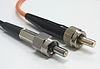
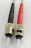
FC Ferrule Connector |
Datacom Telecom Measurement equipment Single-mode lasers |
|
|
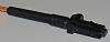
LC Lucent Connector |
High-density connections, SFP and SFP+ transceivers, XFP transceivers |
|
|
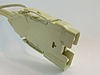
M12 |
Machine, process and plant engineering |
|
|
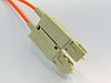
SC Square connector |
Datacom and telecom, GPON; EPON; GBIC |
|
|
MIC |
Fiber distributed data interface(FDDI) |
|
|
MT Mechanical Transfer |
Pre-terminated cable assemblies |
|
|
SC-DC SC-Dual contact |
Datacom and telecom; |
|
|
SMA 905 Sub miniature A |
Industrial lasers, optical spectrometers, military; telecom multimode |
|
|
ST Straight Tip |
Datacom |
|
Integration Notes: What to Verify in the Field
In commissioning and troubleshooting, it is helpful to treat fiber links as engineered circuits with measurable performance. Key parameters include insertion loss (dB), return loss/reflection, and end-to-end optical budget. If a link is marginal, it may operate intermittently (especially across temperature changes or vibration), which can appear as sporadic Ethernet link drops or errors rather than a hard failure.
For industrial Ethernet deployments over fiber, confirm at minimum:
- Fiber type and optics match: single-mode optics with single-mode plant; multimode optics with multimode plant.
- Connector type matches the equipment: LC is typical for SFP/SFP+; SC is common for patch panels and older gear.
- Polarity is correct: TX on one end must land on RX on the other end (often crossed via patching).
- End faces are clean: inspect and clean every time before mating; contamination is a leading cause of loss.
- Bend radius is respected: tight bends can introduce macrobending loss, especially in single-mode runs.
In environments with frequent maintenance access, consider labeling and documenting patching, including fiber type, connector type, and destination ports. This reduces the risk of accidental cross-connection and speeds up fault isolation.
Frequently Asked Questions (FAQ)
Q1: Why are LC connectors so common on modern network equipment?
LC connectors are compact and support high-density patching. They are the dominant interface for SFP and SFP+ optics used in switches, routers, and industrial Ethernet equipment, which makes them common in both enterprise and automation backbones.
Q2: What is the difference between SC and SC-DC?
SC-DC (SC dual contact) is a variation intended to support duplex connectivity more conveniently. In practice, many fiber links are duplex (one strand TX and one strand RX). Connector families can be packaged as duplex assemblies to simplify patching and maintain polarity.
Q3: Can I mix single-mode and multimode components if the connectors fit?
No. Connector fitment does not imply optical compatibility. Single-mode and multimode fibers have different core sizes and are paired with different optics. Mixing them typically results in excessive loss, unstable links, or complete link failure depending on distance and optics type.
Q4: What is the most common cause of fiber link issues during commissioning?
End-face contamination and polarity mistakes are the most common. A single dirty connector can add enough insertion loss to destabilize a link, and incorrect TX/RX mapping will prevent link establishment entirely. A standard practice is to inspect/clean before mating and to verify polarity end-to-end.
Q5: When should an M12 fiber connector be considered?
M12 fiber connectors are commonly used when a rugged, circular, and environmentally tolerant interface is needed in machine, process, and plant engineering. They can be appropriate on equipment exposed to vibration, moisture, or frequent handling where standard patch-panel style connectors are not suitable.