SqrdresizedWTBG__16193.1712846631.png?c=2 "Sqrd resized WT BG png - Sqrd resized WT BG png")

Multiport Gateway (Serial-Ethernet-LonWorks)
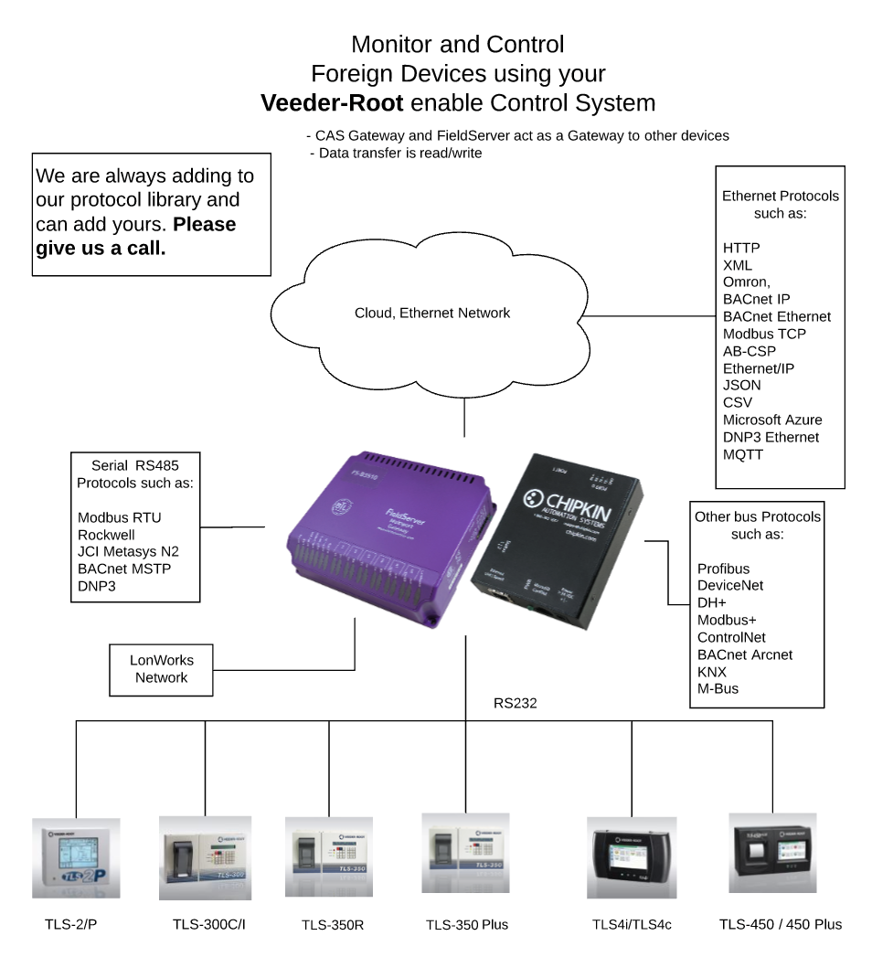
This protocol translator/gateway provides a wealth of features to enable data transfer between different devices and networks utilizing serial, Ethernet or LonWorks ports. The extensive library of FieldServer drivers provides easy interoperability with devices and networks used in building automation, HVAC, fire and process control industries.
The FS-B3510 is one of the FS-X30 Series FieldServers designed to meet the needs of system integrators in designing a complete interoperable system. The FS-B30 Series brings together the powerful FieldServer driver library with state-of-the-art gateway design. This FieldServer includes four serial connections (two RS-232, two RS-485), two Ethernet ports, and a LonWorks port. The multiport design allows for serial-to-serial interfaces or interface from mulitple serial products to an Ethernet or LonWorks network. The two Ethernet ports enable the integrator to connect a PC to download configuration changes without disturbing the system connections and without the additional cost of an external hub.
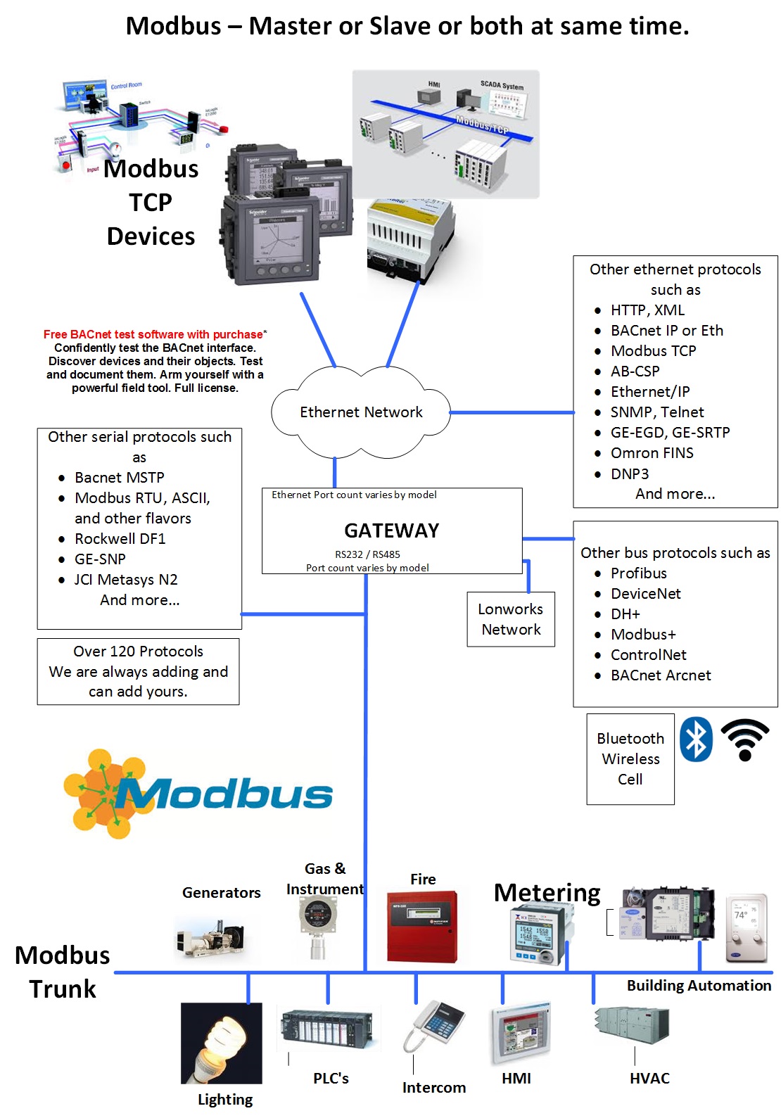
Modbus TCP
The Modbus TCP Driver allows the FieldServer to transfer data to and from devices over Ethernet using Modbus TCP Protocol. The Modbus TCP driver uses port 502. This port is not configurable. The driver was developed for Modbus Application Protocol Specification V1.1a" from Modbus-IDA. The specification can be found at www.modbus.org. The FieldServer can emulate both a Client and a Server simultaneously on the same ethernet port.
The information that follows describes how to expand upon the factory defaults provided in the configuration files included with the FieldServer.
There are various register mapping models being followed by various vendors. To cover all these models FieldServer uses the following three Models
- Modicon_5digit – Use this format where addresses are defined in 0xxxx, 1xxxx, 3xxxx or 4xxxx format. A maximum of 9999 registers can be mapped of each type. This is FieldServer driver’s default format.
- ADU –Application Data Unit address. Use this format where addresses of each type are defined in the range 1-65536
- PDU –Protocol Data unit address. Use this format where addresses of each type are defined in the range 0-65535.
The key difference between ADU and PDU is for example if Address_Type is ADU and address is 1, the driver will poll for register 0. If Address_Type is PDU, the driver will poll for address 1.
Note 1: If vendor document shows addresses in extended Modicon (i.e. 6 digit) format like 4xxxxx then consider these addresses as xxxxx (omit the first digit) and use either ADU or PDU
Note 2: The purpose of providing 3 different ways of addressing the Modbus registers is to allow the user to choose the addressing system most compatible with the address list being used. At the protocol level, the same protocol specification is used for all three with the exception of the limited address range for Modicon_5digit.
Veeder-Root
The Veeder-Root Serial Driver allows the FieldServer to transfer data to and from devices over either RS- 232 or RS-485 ports using Veeder-Root protocol as defined in Veeder- Root Document 576013-635 Revision J. The Veeder-Root Driver supports TLS350 as per Veeder-Root Document 576013-635 Revision Y, and TLS450 as per Veeder-Root Document 577013-950 Revision G. Since the data protocol is the same for the TLS-350+ as for TL-S350, it is assumed that the driver will support the TLS350+ but this has not been tested. The Driver also successfully communicates with the TLS-450 as it has the same data protocol. Please refer to the driver manual for hardware connections.
The FieldServer emulates a Client.
The Veeder-Root Serial Driver is a poll response driver. Only one query or command can be processed at a time.
A limited set of the queries and commands defined in the protocol specification have been implemented. The reason for the limitation is two-fold. Firstly, not all commands/queries will have any meaning to a Server device as they are principally defined to configure the Veeder-Root Device. Secondly, some commands return very complex data sets which cannot be processed in a method suitable for loading into the FieldServer’s Data Arrays.
The driver is capable of exposing its communications statistics which allows them to be monitored using a Server device.
Supported Veeder-Root products
The Veeder-Root Gateway supports the following Veeder-Root Products:
- TLS-450 PLUS Automatic Tank Gauge
- TLS4i / TLS4c Automatic Tank Gauge
- TLS-350 Automatic Tank Gauge
- TLS-350 Plus Automatic Tank Gauge
- TLS-350R Automatic Tank Gauge
- TLS-300C/I Automatic Tank Gauges
- TLS-2/P Automatic Tank Gauge
Specifications
Multiport Gateway (Serial-Ethernet-LonWorks)
Field Connections
- Ethernet Ports – 2: 100 BaseT RJ45 connector (auto MDIX and sensing) with ESD protection
- Serial Ports – 5: 2 x RJ45 RS-232 galvanically isolated with ESD protection. 2 x RS-485 galvanically isolated with ESD protection. 1 x RJ45 RS-232 system port.
- LonWorks – 1: FTT-10 twisted pair. 1000 Network variable capability. LonWorks service pin
- Auxiliary ports – 2: 2 x USB ports. Expansion: Fieldbus connectors available for selected protocol
Environment
- Operating Temperature: 0-60°C (32-140°F)
- Relative Humidity: 10-90% non-condensing
Power Requirements
24V AC (+/-10%) or 12-30V DC @ 12W
Physical Dimensions
- Dimensions (WxDxH): 6.3x5.4x2.0 in.(16.0x13.7x5.0cm)
- Weight: 2.5 lbs (1.5 Kg)
- Input voltage: 24 V DC nominal: 10-30V DC
Other
Configuration/Diagnostic utilities
- Capacity: Base system has 1000 point capability (upgradeable to 10,000 points)
- Mounting Options: Desktop, Wall, Panel Optional: DIN rail
LED Indicators
Power, Run, System Error, Configuration Error, and Node Offline
Ethernet connection– Link OK, Tx/Rx communication activity
RS-232/RS-485 – Tx/Rx communication activity
LonWorks - Activity
Communication, Option, Drivers
Memory upgrade for additional data points
Custom Configuration Service
Drivers available for a wide range of Ethernet and social protocols
Approvals
- CE Marked
- CSA Certified: UL916 Standard and CSA @ 22.2
- DNP 3.0 Tested
- RoHS Compliant
- GOST-R Certified
- FCC: Part 15
- LonMark Certified
- Modbus Tested
- BTL Certified

Manuals
Datasheets
Case Studies
Resources
Additional Information
Modbus - MK10 and 32 Bits Numbers
Scaling in Modbus
Modbus does not provide a method for transporting large or Floating Point numbers or a mechanism for scaling analog values. A 16 bit word can only contain values in the range 0-65535. Only whole numbers are permitted. To work around this many server device manufacturers use multipliers and document them in their manuals. For example, to report a temperature of 58.5 the device reports a value of 585, and makes a note in the manual that the master should scale by 10. This scaling is achieved by adopting a convention between the client and the server.
What about large numbers > 65535
Modbus does not provide a mechanism but 3 important schemes are widely used.
Long Integers – Two consecutive 16 bit words are interpreted as a 32 bit long integer.
MK10 values – Two consecutive words are used. The 1st reports the number of units and the 2nd reports the number of 10,000’s.
Floating Point Numbers – Two consecutive words are used and a scheme. These schemes are conventions and not all servers or clients support them.
The protocol does not identify these big numbers. Only the vendor docs do.
What we mean by this is – if you look at the byte stream in a Modbus message there is no way of telling whether you are looking at two consecutive 16 bit words, or two consecutive words that should be interpreted as floating point, long or MK10 formats. Because of this you always have to look to the vendor docs.
Modbus - Reading Vendor Modbus Maps
Reading Vendor Modbus Maps
If you are reading the documentation for sensor blocks, valves, and other devices, you must keep in mind that some vendors may document their hardware in different ways.
According to the Modbus standard, addresses are simply integers from 0 to 65,535 with the different address ranges being referred to as coils, holding registers, etc. However, some vendors will document their hardware using numerical prefixes which are not actually part of the Modbus address. This originated from some models of PLCs which used the Modbus communications protocol, and which also used numerical prefixes in their internal data table. This is similar to using “I”, “Q”, “V”, etc. as address prefixes in IEC type PLCs.
However, it is important to remember that these numerical prefixes are documentation methods and are not part of what the Modbus protocol itself sends as part of the messages. A difference in documentation methods does not affect the compatibility of the protocol itself.
These prefixes are they mentioned anywhere in the Modbus standard, but the following shows how they are typically used in documentation based on this older convention:
- 0xxxx – Coils.
- 1xxxx – Discrete inputs.
- 3xxxx – Input registers.
- 4xxxx – Holding registers.
Note that there is no 2xxxx address prefix.
In addition to numerical prefixes, some documentation will refer to protocol addresses (addresses start at 0), while other documentation will refer to data model addresses (addresses start at 1). That is, the first holding register may be 0 or 1 (or 40000 versus 40001 using prefixes). However, this has no bearing on what gets sent over the wire as a Modbus message. For a Modbus protocol message, the lowest address is always “0”, not “1”.
Modbus - Protocol Specifications
Protocol Specifications
Modbus - Flavors of Modbus
Flavors of Modbus
RTU:
Common
Binary Protocol.
Active Master-passive Slave
Serial
Supported by FieldServers, QuickServers, CAS gateways
ASCII:
Similar to ModbusRTU but for each byte in an RTU message, there are 2 bytes in an ASCII message. The 2 bytes are the humand readable form of the single hex byte.
Eg RTU byte = 0x03 (Hex). ASCII bytes = ‘0’ and ‘3’ ie 0x30 and 0x33
Active Master-passive Slave
Serial
Supported by FieldServers, QuickServers
Jbus:
Modbus had the limitation of a max of 9999 items of each type. Ie only 9999 holding registers. However the protocol message allows 65k items to be addressed. JBUS allows all 65k items to be read/written. Other than that it is identical to RTU
Active Master-passive Slave
Serial
Supported by FieldServers, QuickServers, CAS gateways
TCP/IP:
Uses TCP/IP connection based Ethernet communications
Encapsulates RTU messages and adds a header.
A single slave can respond to multiple masters
Many slaves ignore the NodeID field in the message.
Supported by FieldServers, QuickServers, CAS gateways
MB Plus:
Proprietary coax networking layer
2 Mbits/sec
Supported by FieldServers, CAS gateways
Articles
Veeder-Root - Printing Setup Report
Lonworks - Can you show me an example of typical FieldServer / QuickServer Veeder Lonworks points
How do I Change the Connection Parameters on a Veeder Root TLS – 3XX Panel
Veeder-Root - How do I find a typical list of points served for TLS (Veeder) Data
Veeder-Root - How to print Veeder-Root Setup Report for TLS-300 and TLS-350
Veeder-Root: Decoding TLS-350 Series In-Tank Inventory Terminology
Case Study - Modbus RTU and Veeder Root to Ethernet IP
Table 2 Modbus Registers
Modbus - Convert between Modbus Flavors
How Real (Floating Point) and 32-bit Data is Encoded in Modbus RTU Messages
How to Create a Modbus client in C#
Modbus - 32 bit numbers
Modbus - Multiple Masters of one slave
ModbusTCP - Modbus Transaction Identifier
Modbus - There are (were) a Max of 9999 points of each data type
ModbusTCP - What type of protocol is Modbus TCP
ModbusTCP - What do you have that can help me convert my Modbus TCP data
Checking Communication Between Device and PC: Modbus TCP
Simplified Modbus-to-Modbus Integration with FieldServer Devices
ModbusTCP - Can you give me an example of a Modbus/TCP to BACnet/IP configuration
Using Modbus Scanner to Write Digitrip 3000 (Protective Relays) Control Registers
Modbus - What is Modbus? (extended article)
Modbus - What is the Modbus Transaction Identifier
Modbus - A list of Useful tools and applications for Modbus
How to Make the CAS Modbus Scanner Read A Modbus 6 Digit Address (JBUS)
Serial COM Connections: PuTTY or RealTerm (HyperTerminal Alternative)
Testing Modbus communication
Modbus Frequently Asked Questions (FAQ) and Answers
FS-8704-03 – Modbus TCP
Modbus Protocol Specification
Modbus Specifications and Implementation Guides
MODBUS Exception Responses
Useful Links
Logos

