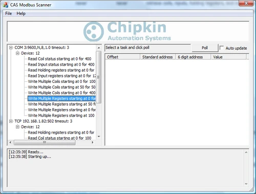
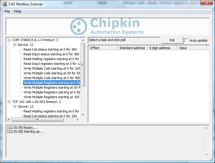
What is the CAS Modbus Scanner?
The CAS Modbus Scanner is a diagnostic and discovery utility used to communicate with Modbus-enabled devices. It allows technicians and engineers to read coils, discrete inputs, input registers, and holding registers from Modbus RTU and Modbus TCP devices.
Retrieved values can be displayed in multiple formats including Binary, HEX, Uint16, Int16, Uint32, Int32, and Float32. This makes the tool ideal for commissioning, troubleshooting, and validating Modbus register mappings.
When the Modbus slave address or communication parameters are unknown, the scanner can automatically discover devices by testing address ranges, function codes, offsets, and register lengths, reporting valid responses and exceptions.
Key Features
- Read coils (0xxxx), discrete inputs (1xxxx), input registers (3xxxx), and holding registers (4xxxx)
- Supports Modbus RTU and Modbus TCP
- Works over RS232, RS485, and Ethernet
- Automatic discovery of devices with unknown slave addresses
- Multiple simultaneous connections
- Tested with hundreds of third-party Modbus devices
- View data in Binary, HEX, Uint16, Int16, Uint32, Int32, and Float32 formats
- Simple, technician-friendly user interface
- 100% free to use, no registration required
Downloads
Please review the License Agreement before downloading the utility.
.png)

Manuals and Technical Resources
Modbus for Field Technicians (Free eBook)
This free eBook guides technicians through fundamental and advanced Modbus concepts commonly encountered in real-world field applications.
Frequently Asked Questions – CAS Modbus Scanner
The following questions address common use cases and technical considerations when using the CAS Modbus Scanner for Modbus RTU and Modbus TCP troubleshooting and validation.
What is the CAS Modbus Scanner used for?
It is used to test communication with Modbus devices by reading coils, discrete inputs, input registers, and holding registers to verify wiring, addressing, and register mapping.
Does it support Modbus RTU and Modbus TCP?
Yes. The scanner supports Modbus RTU over RS232 and RS485, as well as Modbus TCP over Ethernet.
Can it discover devices with unknown slave addresses?
Yes. The tool can automatically scan address ranges to identify responsive devices.
What data formats are supported?
Binary, HEX, Uint16, Int16, Uint32, Int32, and Float32.
What is required to connect to RS485?
A USB-to-RS485 adapter is typically required. See USB to RS485 converter options.
Why am I getting no response?
Common causes include incorrect serial settings, incorrect slave address, wiring or termination issues, or incorrect IP/port for Modbus TCP.
Is the CAS Modbus Scanner free?
Yes. It is free to download and use, with no registration required.
Customer Support
Chipkin provides full support for the products we sell. For technical support, sales, or customer service, call 1 (866) 383-1657.
Modbus RTU
The Modbus RTU driver allows our FieldServer gateways to transfer data to and from devices over either RS-232 or RS-485 using Modbus RTU protocol. The Gateways are capable of being used as port expanders and can emulate either a Server or Client. The FieldServer is capable of supporting devices that use two Modbus Registers to transfer IEEE floating point format.
The information that follows describes how to expand upon the factory defaults provided in theconfiguration files included with the FieldServer.
There are various register mapping models being followed by various vendors.
- To cover all these models FieldServer uses the following three Models
- Modicon_5digit – Use this format where addresses are defined in 0xxxx, 1xxxx, 3xxxx or 4xxxxformat. A maximum of 9999 registers can be mapped of each type. This is FieldServer driver’sdefault format.
- ADU –Application Data Unit address. Use this format where addresses of each type are definedin the range 1-65536
- PDU –Protocol Data unit address. Use this format where addresses of each type are defined inthe range 0-65535.
The key difference between ADU and PDU is for example if Address_Type is ADU and address is 1, thedriver will poll for register 0. If Address_Type is PDU, the driver will poll for address 1.
Modbus TCP
The Modbus TCP Driver allows the FieldServer to transfer data to and from devices over Ethernet using Modbus TCP Protocol. The Modbus TCP driver uses port 502. This port is not configurable. The driver was developed for Modbus Application Protocol Specification V1.1a" from Modbus-IDA. The specification can be found at www.modbus.org. The FieldServer can emulate both a Client and a Server simultaneously on the same ethernet port.
There are various register mapping models being followed by various vendors. To cover all these models FieldServer uses the following three Models
- Modicon_5digit – Use this format where addresses are defined in 0xxxx, 1xxxx, 3xxxx or 4xxxx format. A maximum of 9999 registers can be mapped of each type. This is FieldServer driver’s default format.
- ADU –Application Data Unit address. Use this format where addresses of each type are defined in the range 1-65536
- PDU –Protocol Data unit address. Use this format where addresses of each type are defined in the range 0-65535.
The key difference between ADU and PDU is for example if Address_Type is ADU and address is 1, the driver will poll for register 0. If Address_Type is PDU, the driver will poll for address 1.
Note 1: If vendor document shows addresses in extended Modicon (i.e. 6 digit) format like 4xxxxx then consider these addresses as xxxxx (omit the first digit) and use either ADU or PDU
Note 2: The purpose of providing 3 different ways of addressing the Modbus registers is to allow the user to choose the addressing system most compatible with the address list being used. At the protocol level, the same protocol specification is used for all three with the exception of the limited address range for Modicon_5digit.
Specifications
Supported Applications and System Requirements
The CAS Modbus Scanner is used to quickly determine the correct communication parameters for Modbus devices, including serial port settings and slave addresses. The tool automates the process by testing multiple parameter combinations and clearly reporting which settings successfully establish communication.
The scanner supports both RS232 and RS485 Modbus RTU networks and can be used to discover a single device or multiple slave devices on the same bus. When connecting to an RS485 network from a laptop or PC, a USB-to-RS485 converter is required.
- Supported operating systems: Windows 2000, XP, Vista, Windows 7, Windows 8, and Windows 10 (32-bit and 64-bit)
- Minimum of 10 MB free disk space
- Modbus RTU over RS485 requires an RS485 interface. A USB-to-RS485 converter such as the ACON U-01 can be used

Additional Information
Modbus - Protocol Specifications
Protocol Specifications
Modbus - Reading Vendor Modbus Maps
Reading Vendor Modbus Maps
If you are reading the documentation for sensor blocks, valves, and other devices, you must keep in mind that some vendors may document their hardware in different ways.
According to the Modbus standard, addresses are simply integers from 0 to 65,535 with the different address ranges being referred to as coils, holding registers, etc. However, some vendors will document their hardware using numerical prefixes which are not actually part of the Modbus address. This originated from some models of PLCs which used the Modbus communications protocol, and which also used numerical prefixes in their internal data table. This is similar to using “I”, “Q”, “V”, etc. as address prefixes in IEC type PLCs.
However, it is important to remember that these numerical prefixes are documentation methods and are not part of what the Modbus protocol itself sends as part of the messages. A difference in documentation methods does not affect the compatibility of the protocol itself.
These prefixes are they mentioned anywhere in the Modbus standard, but the following shows how they are typically used in documentation based on this older convention:
- 0xxxx – Coils.
- 1xxxx – Discrete inputs.
- 3xxxx – Input registers.
- 4xxxx – Holding registers.
Note that there is no 2xxxx address prefix.
In addition to numerical prefixes, some documentation will refer to protocol addresses (addresses start at 0), while other documentation will refer to data model addresses (addresses start at 1). That is, the first holding register may be 0 or 1 (or 40000 versus 40001 using prefixes). However, this has no bearing on what gets sent over the wire as a Modbus message. For a Modbus protocol message, the lowest address is always “0”, not “1”.
Modbus - MK10 and 32 Bits Numbers
Scaling in Modbus
Modbus does not provide a method for transporting large or Floating Point numbers or a mechanism for scaling analog values. A 16 bit word can only contain values in the range 0-65535. Only whole numbers are permitted. To work around this many server device manufacturers use multipliers and document them in their manuals. For example, to report a temperature of 58.5 the device reports a value of 585, and makes a note in the manual that the master should scale by 10. This scaling is achieved by adopting a convention between the client and the server.
What about large numbers > 65535
Modbus does not provide a mechanism but 3 important schemes are widely used.
Long Integers – Two consecutive 16 bit words are interpreted as a 32 bit long integer.
MK10 values – Two consecutive words are used. The 1st reports the number of units and the 2nd reports the number of 10,000’s.
Floating Point Numbers – Two consecutive words are used and a scheme. These schemes are conventions and not all servers or clients support them.
The protocol does not identify these big numbers. Only the vendor docs do.
What we mean by this is – if you look at the byte stream in a Modbus message there is no way of telling whether you are looking at two consecutive 16 bit words, or two consecutive words that should be interpreted as floating point, long or MK10 formats. Because of this you always have to look to the vendor docs.
Modbus for Field Technician - Free Booklet
ModbusRTU - ModbusTCP - Port Expansion
Port Expansion
FieldServer can easily be configured to allows a Modbus RTU client to talk to a ModbusTCP server and vice versa. You do not need to tell the FIeldServer which registers to map from one to the other. You simply configure the FieldServer telling it which port and protocol to use for each node.
In port expansion mode configuration can be moinimal. Tell the gateway which nodes are on which port and set the port settings.
ModbusRTU - Scaling and Bit Packing
Scaling / Bit Packing
FieldServers can scale data and manipulate values using some binary logic and arithmetic functions. Scaling can be applied to each block of Modbus Data read / served.
- Move to change type : Convert from any FIeldServer Data Type to any other.
- Move to pack/unpack bits and bytes: It’s possible to address each bit in a 8,16 or 32 bit data element by using the packed data types.
- Move to change byte/word order: Handle the endianess of the remote system easily.
- Convert to/from Float, MK10, IEE754, 32 bit, 16 bit, 8 bit numbers
- Move conditionally:
- Perform Arithmetic Operation: + – * div sqrt, sqr ,
- Perform Binary Logic Operation: And, Or, Not, >, >= , <, <=
Most functions can be configured to occur on a configurable period or on update of the data source.

ModbusRTU - Supported Data Types
Supported Data Types
Bit
Byte
16 Bit Integer Signed
16 Bit Integer Unsigned
32 Bit Integer Signed
32 Bit Integer Unsugned
32 Bit Packed Bit
8 Bit Packed Bit
4 byte FLoating Point Numbers
ModbusRTU - Supported Functions
Supported Modbus Functions
01 Read Discrete Output Status (0xxxx)
02 Read Discrete Input Status (1xxxx)
03 Read Output Registers (4xxxx)
04 Read Input Registers (3xxxx)
05 Force Single Coil (0xxxx)
06 Preset Single Register (4xxxx)
15 Force Multiple Coils (0xxxx)
16 Preset Multiple Registers (4xxxx)
Modbus - Flavors of Modbus
Flavors of Modbus
RTU:
Common
Binary Protocol.
Active Master-passive Slave
Serial
Supported by FieldServers, QuickServers, CAS gateways
ASCII:
Similar to ModbusRTU but for each byte in an RTU message, there are 2 bytes in an ASCII message. The 2 bytes are the humand readable form of the single hex byte.
Eg RTU byte = 0x03 (Hex). ASCII bytes = ‘0’ and ‘3’ ie 0x30 and 0x33
Active Master-passive Slave
Serial
Supported by FieldServers, QuickServers
Jbus:
Modbus had the limitation of a max of 9999 items of each type. Ie only 9999 holding registers. However the protocol message allows 65k items to be addressed. JBUS allows all 65k items to be read/written. Other than that it is identical to RTU
Active Master-passive Slave
Serial
Supported by FieldServers, QuickServers, CAS gateways
TCP/IP:
Uses TCP/IP connection based Ethernet communications
Encapsulates RTU messages and adds a header.
A single slave can respond to multiple masters
Many slaves ignore the NodeID field in the message.
Supported by FieldServers, QuickServers, CAS gateways
MB Plus:
Proprietary coax networking layer
2 Mbits/sec
Supported by FieldServers, CAS gateways
Logos